

Introduction: How to Make a Cool Robot From an RC Car

This cool project is for high school students or any hobbyist who wants to make a cool robot.
I was trying to make an interactive robot long time but making one is not easy if you don't know any electronics or special programming languages. Now there is a programming language called nqBASIC, that is totally free, to make your very own robot.
Step 1: What You Need?


You will need some parts for this cool project.
1) Go and find an RC car that has two DC motor in it. I found a very cheap car called thunder tumbler for $12.
Picture is below.
2) You will need a Servo Sensor controller card called SSMI. Here is the link to get it
http://www.technologicalarts.ca/catalog/product_info.php?currency=USD&products_id=276
3) You will need a micro controller for this board called NanoCore12DX
http://www.technologicalarts.ca/catalog/product_info.php?cPath=50_36_92&products_id=429
4) You need two sensor if you want to make your robot interactive
http://www.technologicalarts.ca/catalog/product_info.php?cPath=25_147&products_id=188
5) Serial cable to connect your computer to your robot to program.
http://www.technologicalarts.ca/catalog/product_info.php?cPath=26&products_id=38
6) A cool robot language developed for this product is called nqBASIC. Go to http://www.nqbasic.com and download for free. You can also ask questions from their forum.
7) 4 AA batteries (alkaline or rechargeable)
Step 2: Take RC Car Apart

1) I took out all of the electronics. Cut cables from the controller unit inside the RC car,
leaving only the battery, because it was just right to power the SSMI (Servo/Sensor/Motor Interface Board for NanoCore12DX ).
Step 3: Attached DC Cables and Battery Cables

The R/C car's two DC motors already had cables on them so I attached them to the pluggable connectors (comes with SSMI board) on my SSMI. I did the same with the battery cable.
Step 4: LED Cables


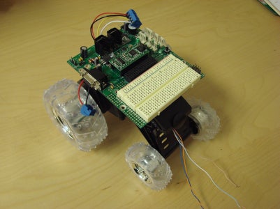

There are 4 cables left. They are thin ones. These are the cables that come from the wheels. This RC car has LEDs inside the back wheels. Two cables come from each wheel. Your robot can be pretty with these LEDs. I decided to use these LEDs to make the robot more fun. You can see these cables from the picture.
I mounted a black piece of plastic that came from the back of the car onto the front of the car to make a nice flat surface to mount SSMI board. I used velcros to mount SSMI on it. You can use double sided tape and some tie wraps if you want.
Then I inserted the LED cables through holes in the front of the car. I mounted SSMI on the car.
Then I plugged DC motors and battery plugs to their locations.
Step 5: Connect LED Cables to the SSMI Board


Then plug the LED cables to the right places. You need to learn from the SSMI board manual which connectors you can use. Go ahead and plug them into the same places I did. Later you can learn to put these cables to different places if you want.
See pictures
Step 6: Connect Sensors


Connect the sensor cables to the right places.
Step 7: Your Robot Is Ready to Roll

Your robot hardware is ready. Now you need to program it.
Step 8: Install the Software

Go to http://www.nqbasic.com and download the software from the website. All instructions are on the website-- how to install and make your computer ready for it. There is also a cool YouTube video which shows how to register the software for free.
This programming language is totally free. Don't hesitate to register. Otherwise you can't compile your code.
Step 9: Ready to Program

Connect your serial cable from your computer serial port to the SSMI serial port.
1) Launch nqBASIC and select project and newproject
2) give a name to your project and save it.
3) It will ask you which nanocore module you are using, select NanoCore12DX from the list. This is the only module that works with SSMI.
4) Select File/New file. It will ask if you want to add this file to your project. Say Yes.
5) Give a name for the file and click Save.
Step 10: Copy and Paste the Source Code
/* Copy from here to the end of this text
Example for DIP32 (8mHz)
*/
dim M00 as new pwm(PP0)
dim M01 as new pwm(PP1)
dim M11 as new pwm(PP2)
dim M10 as new pwm(PP3)
dim IR1 as new ADC(PAD05) //ADC object for Sharp Sensor (Front)
dim IR1Result as new byte
dim IR2 as new ADC(PAD03) //ADC object for Sharp Sensor (Back)
dim IR2Result as new byte
dim myChar as new byte //Variable to store received characters
dim S as new SCI(PS0,PS1) //SCI object
dim SPK as new DIO(PM4) // Using Speaker on the SSIM
const ontime = 20
dim duration as new word
Const A2 = 2273 // Music notes
Const A3 = 1136 // Music notes
Const A4 = 568 // Music notes to make sound when robot sees something
dim WLED1 as new DIO(PM2) //LEDs on the wheels
dim WLED2 as new DIO(PM3) //LEDs on the wheels
dim loop as new byte
Const OFF = 0
Const ON = 1
Const FOREVER = 1
Const A = 200
Const B = 10
Const DEL_1MSEC = 1000
sub DelayMsec (in byte milliseconds)
while (milliseconds > 0)
System.Delay (DEL_1MSEC) //Delay 1000 microsecond to make 1 millisecond
milliseconds = milliseconds - 1
end while
end sub
sub stop() // to make motors stop
M00.PWM_Start(PWM_MAIN_CLK,0,250,250)
M01.PWM_Start(PWM_MAIN_CLK,0,250,250)
M10.PWM_Start(PWM_MAIN_CLK,0,250,250)
M11.PWM_Start(PWM_MAIN_CLK,0,250,250)
end sub
sub goback() // robot will go back
M00.PWM_Start(PWM_MAIN_CLK,0,250,180)
M01.PWM_Start(PWM_MAIN_CLK,0,250,250)
M10.PWM_Start(PWM_MAIN_CLK,0,250,180)
M11.PWM_Start(PWM_MAIN_CLK,0,250,250)
end sub
sub turnright() // turn the robot to the right
M00.PWM_Start(PWM_MAIN_CLK,0,250,250)
M01.PWM_Start(PWM_MAIN_CLK,0,250,180)
M10.PWM_Start(PWM_MAIN_CLK,0,250,250)
M11.PWM_Start(PWM_MAIN_CLK,0,250,250)
end sub
sub turnleft() // turn the robot to the left
M00.PWM_Start(PWM_MAIN_CLK,0,250,250)
M01.PWM_Start(PWM_MAIN_CLK,0,250,250)
M10.PWM_Start(PWM_MAIN_CLK,0,250,250)
M11.PWM_Start(PWM_MAIN_CLK,0,250,180)
end sub
sub goahead() // make the robot forward
M00.PWM_Start(PWM_MAIN_CLK,0,250,250)
M01.PWM_Start(PWM_MAIN_CLK,0,250,180) //left dc
M10.PWM_Start(PWM_MAIN_CLK,0,250,250)
M11.PWM_Start(PWM_MAIN_CLK,0,250,180) //right dc
end sub
sub wait3() // my own delays
DelayMsec(A)
DelayMsec(A)
DelayMsec(A)
end sub
sub wait4()
DelayMsec(A)
DelayMsec(A)
DelayMsec(A)
DelayMsec(A)
end sub
sub wait5()
DelayMsec(A)
DelayMsec(A)
DelayMsec(A)
DelayMsec(A)
DelayMsec(A)
end sub
sub wait10() //long delay
loop = 1
while(loop < 11)
DelayMsec(A)
loop =loop + 1
end while
end sub
sub playsound() // to play the notes
duration = ontime
while(duration > 0)
SPK.PIN_Out(PM4,ON)
system.Delay(A2)
SPK.PIN_Out(PM4,Off)
system.Delay(A2)
duration = duration - 1
end while
DelayMsec(B)
duration = ontime
while(duration > 0)
SPK.PIN_Out(PM4,ON)
system.Delay(A3)
SPK.PIN_Out(PM4,Off)
system.Delay(A3)
duration = duration - 1
end while
DelayMsec(B)
duration = ontime
while(duration > 0)
SPK.PIN_Out(PM4,ON)
system.Delay(A4)
SPK.PIN_Out(PM4,Off)
system.Delay(A4)
duration = duration - 1
end while
DelayMsec(B)
end sub
main
PWM.PWM_Res_PP0145 (TIMER_DIV_16, 0)
PWM.PWM_Res_PP23 (TIMER_DIV_16, 0)
S.SER_Setup(SER_BUFFER_4,BAUD9600) //Setup SCI and allow 4 characters to be buffered
System.INTS_On () //TURN ON INTERRUPTS!
S.SER_Put_string("This is a test ")
S.SER_Put_char ('\n')
S.SER_Put_char ('\r')
while (FOREVER)
IR1.ADC_Start (WAIT, ADC_MODE_8ONCE) // Read value from the front sharp sensor
IR1.ADC_Read (PAD05,IR1Result)
IR2.ADC_Start (WAIT, ADC_MODE_8ONCE) // Read value from the back sharp sensor
IR2.ADC_Read (PAD03,IR2Result)
S.SER_Put_decimal(IR2Result,FILLUP_SPACE) // send the value to the windows hyper terminal
S.SER_Put_char ('\n') // make a new line on the hyper terminal
S.SER_Put_char ('\r')
if ((IR1Result == 25) or (IR1Result > 25))
stop()
playsound()
wait5()
WLED1.PIN_Out(PM2,ON)
WLED2.PIN_Out(PM3,ON)
goback()
wait5()
if ((IR2Result == 25) or (IR2Result > 25))
stop()
playsound()
wait5()
turnleft()
wait3()
goahead()
end if
turnright()
wait3()
else
goahead()
end if
if ((IR2Result == 25) or (IR2Result > 25))
WLED1.PIN_Out(PM2,ON)
WLED2.PIN_Out(PM3,ON)
stop()
wait5()
turnright()
wait3()
WLED1.PIN_Out(PM2,OFF)
WLED2.PIN_Out(PM3,OFF)
goahead()
wait3()
else
goahead()
end if
end while
end main
Step 11: Compile and Load in to Your Robot
Make sure you put batteries in your robot and turn it on.
You should see the green Power LED glowing on the SSMI.
On the Nanocore12DX module there is a little switch, make sure it's in load position.
Press the reset switch on the SSMI.
Go to nqbasic and select Build and load.
It will compile your code and load it into your robot.
Take the serial cable off from your robot and change switch from load to run position on the NanoCore12DX module.
Put your robot on a flat surface and press reset button on the SSMI.
Congratulations!
If you have any problems with these steps, please don't hesitate to write on the nqBASIC forum. I will be there and answer all your questions.
Have fun!


