

Introduction: How to Reassemble a Wicked Lasers EVO


So for what ever reason someone took apart a EVO laser and gave the parts to you. Now what do you do?
Having had this happen to me thought I would help other in their quest to reassemble this puzzle.
Step 1: Find All the Parts

First step is to make sure you have all the parts. In my case I got everything but 1 nylon screw.
Step 2: Verify the Laser Still Works.


Test the laser diode before proceeding. Ours was damaged when we got it and needed repair. Luckily it turned out to just be just a cracked SMT resistor. A new resistor and a few seconds with a soldering iron and it was ready for test. To force the laser on short pin 5 of the expansion to ground (as shown or pin 8 of the expansion connector). Next hook up power and ground from 2 AA batteries. The spring terminal on the laser goes to the - (negative) side of the batteries. The + (positive) side of the batteries needs to connect to the brass body of the laser diode. Note the laser will turn on as soon as both connections are made so point it in a safe direction and wear the laser safety glasses!
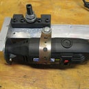
Step 3: Start Assembly

Before assembling the lenses make sure they are clean! Screw the lens assembly on the laser diode block finger tight.
Step 4:

Next step is to slide the laser board assembly into the plastic holder. Slide it into the end of the plastic with a notch laser end first. Make sure to line up the PCB with the groove in the plastic part.
Step 5:


Slide in the laser/plastic holder assembly into the outer body. Slide it in laser diode end first through the battery end of the outer case. line up the button hole between the two parts. Do NOT push the PCB and holder in all the way at this time!
Step 6:


The next step is to sort out the wires to the button. The easiest way to do this is to use a 3V coin sell. Try all the combinations of wires across the battery until the button lights up. Note which wire is hooked to the + and - side of the battery those are the LED + / - and the remaining 2 are the switch wires.
On my switch the wire colors are:
White = LED +
Blue = LED -
Red = switch
Black = swtich
Step 7:


For the next step feed the button wires in the button hole and pull them out the battery hole. Pull the pcb out as far as you can until the laser diode hits the button wire. The next step is soldering the wires to the PCB a set of small needle nose pliers are VERY helpful.
White (LED +) => solders to pad P4
Blue (LED -) => solders to pad P3
Red (switch) => solders to pad P2
Black (switch) => solders to pad P1
Double check for shorts before continuing.
Step 8: Laser Testing

Now is a good time to retest the laser and verify the button works properly. Again hook the - (negative) side of the battery to the spring terminal and the + (positive) side of the batter to the body of the case. Make sure the LED lights up and starts blinking. If you install the jumper and enter the magic button sequence the laser should turn on as well. Do not leave the laser running to long since the thermal joint to the case is poor and the laser may overheat.
Step 9: More Assembly


Once verified tuck the wires back into the laser and start sliding the core assembly in place. Make sure the header lines up with the square hole on the back and the button fits in the hole and the symbol is lined up in the correct direction. The little board with the spring terminal just presses into the end of the inner plastic holder.
Step 10:


Next step install the "lens retainer ring" (for lack of a better name). If you don't own a proper pair of optical spanner wrenches like me a pair of tweezers work well. Before tightening the ring down make sure the button is fully in and in the proper rotation. Make sure to hold the button down while tightening the lens retainer ring. Tighten the ring just past finger tight. This will pinch the body of the switch and hold it in place.
Once that is done screw in the outer lens end cap.
Step 11:


The next step is to put the 2 small set screws in the MIDDLE two holes on the button side of the laser case. These press the laser body against the case. Tighten them down just past finger tight.
Step 12:

Put the button side shield back on and put the two small flat head screws in. DO NOT tighten more than finger tight. The screws are VERY easy to strip.
Step 13:


Install the jumper on the bottom 2 pins as shown. This enables normal mode for the laser. If the jumper is left off the button led will blink fast and the laser will not turn on.
Step 14:


Put the side shield on over the expansion port. DO NOT tighten more than finger tight. The screws are VERY easy to strip.
Step 15:


Next step is to assemble the switch end cap. See the first image for the order the parts go together in.
Put the white insulator ring inside the spanner nut. Put the brass battery terminal on the end of the small spring. Put the larger spring over the switch it should ride up on a lip and stays in place. Place the button cap in the switch case letter side down. Install the switch sub assembly into the switch case large spring end first. Then slide the white insulator and spanner nut over the brass battery terminal so the nut is away from the switch assembly. Tighten the spanner nut down just past finger tight.
Step 16:


Next up is assemble the battery terminal into the main body. First insert the small pin into the small plastic tube. Make sure the end of the pin with a clip is on the end of the tube with the ridge as shown. Insert this assembly into the end of the main body as poorly shown so the clip end is up. Put the small silver metal T bar into the insulator block as shown. Put the block into the main body as shown. Make sure the flat side of the insulator block is lined up with the safety key hole on the pocket clip of the main body. Install the safety key and make sure it is fully seated. Install the 2 metal screws in the holes isolated from the silver metal T bar. Tighten down the screws just past finger tight. Install the 2 nylon screws (I only had one) into the T bar holes. Only tighten these down finger tight at most else they will strip. Also this set the retention force of the safety key.
Step 17:

Screw the button assembly onto the main body. Add batteries and screw the laser head onto the main body.
If all went well the laser should now be back to normal and functional again!
Enjoy.


