

Introduction: How to Use Pulse-Width Modulation
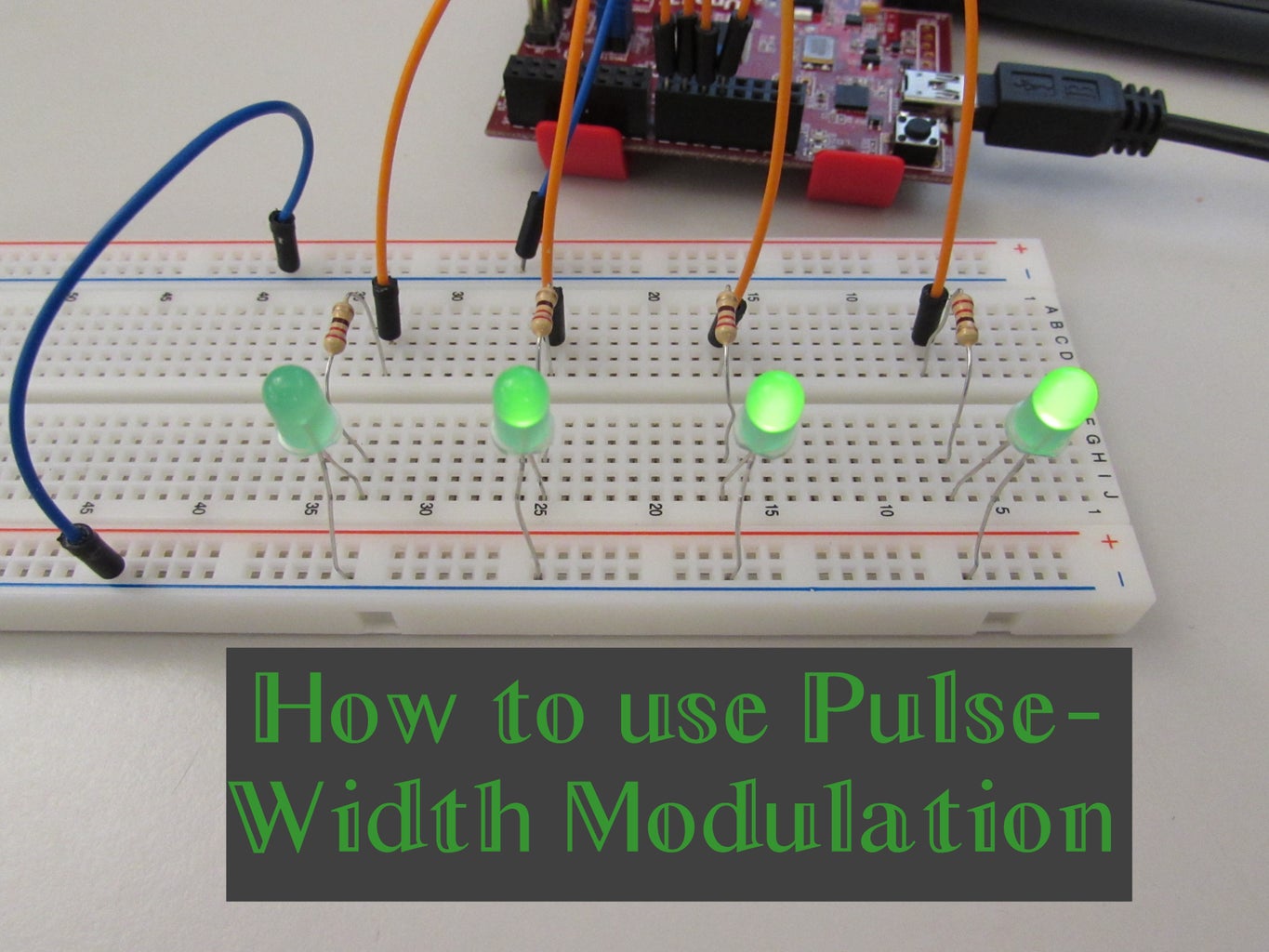


Many of you have likely seen lights that seem to "breathe" or have heard sounds that get steadily louder and softer. A large majority of these are achieved through pulse-width modulation (pwm).
Despite the complex sounding name (at least to me), pwm is surprisingly easy to implement and use. To see where I originally learned about pwm, check out Digilent's Learn Module on Pulse-Width Modulation.
Step 1: Materials That I Used
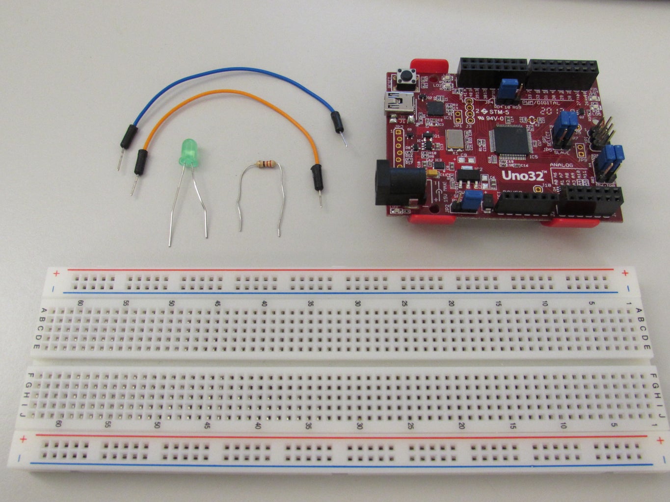
I only used a few materials in order to visualize the pwm signal. What I ended up using was:
- Digilent's chipKIT Uno32
- 1 LED
- One 220 Ohm resistor
- a breadboard
- jumper wires
To program the Uno32, I used the free MPIDE software available from chipKIT.
Step 2: What Is It?
Great question!
Pulse-width modulation is a way to convert a digital signal into an analog signal. The reason why we would want to do this is because digital signals are only ever fully on (high) or fully off (low), where analog signals are able to hit any value in between.
Granted, we could use a resistor to reduce the voltage of a fully on digital signal, but as soon as we want to be able to hit a broad range of in between values, we would find that one resistor (or multiple resistors to choose from) quickly becomes cumbersome and inadequate.
Step 3: The Theory Behind Pwm
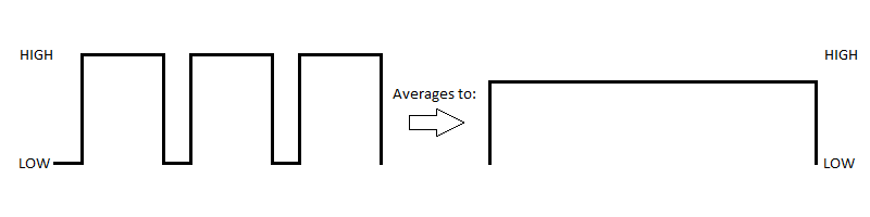
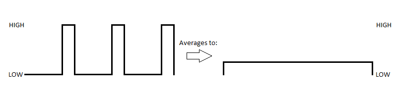
The "pulse-width" in pwm refers to how long the digital signal is held high. The "modulation" portion means that we modulate, or control, how often the digital signal switches between high and low values. When we switch between high and low signals faster than our eyes can detect, we are able to see a variety of voltage values.
If the digital signal is high more often than low, an overall higher voltage (but still less than fully on) will be observed. If the digital signal is low more often than high, an overall lower voltage (but still greater than fully off) will be observed.
Step 4: Operating a Pwm Signal
While knowing how a pwm signal works in principle is nice, it is arguably better and more useful to know how you would choose a particular average voltage and actually implement a pwm signal on a circuit.
The way that a pwm signal works, mathematically, is through a ratio of how long you want the digital signal to be high in a particular period (a consistent length of time between pulses) compared to how long the digital signal could be high (i.e. the full period). This ratio is known as the duty cycle.
For many microcontrollers, such as the one I will be using, there are digital pins that are designated to be capable of pwm, so it is not necessary to know the exact length of time that a period is; this is all handled by the microcontroller. If you want to know how this is done by the hardware in the microcontroller, check out Digilent's How Hardware Implements Pulse-Width Modulation Learn Module.
Step 5: Choosing a Pwm Value

However to know what period is so that the duty cycle is accurate, we need to know how big the timers on the microcontroller are. The Uno32 timers are 8 bits long so this means that the maximum value that the timers can hold (and consequently the length of the period) is 255 and have a minimum value of 0. This means that when we write the pwm signal to the pin, we will be restricted between those values.
The reason we have a restriction in the first place is because the function we will use to implement the pwm signal, analogWrite (since pwm essentially changes a digital signal into an analog signal), can accept values above 255. While this should not damage the LED (or whatever component you happen to be using), you will not be able to see any difference between 255 and the maximum analogWrite value of 1023 because the digital pins on the Uno32 are electrically limited to 3.3V.
With this in mind, we are able to create the equation above where the V with the bar above it is the resulting average voltage for a particular pwm value.
Step 6: Setting Up the Circuit
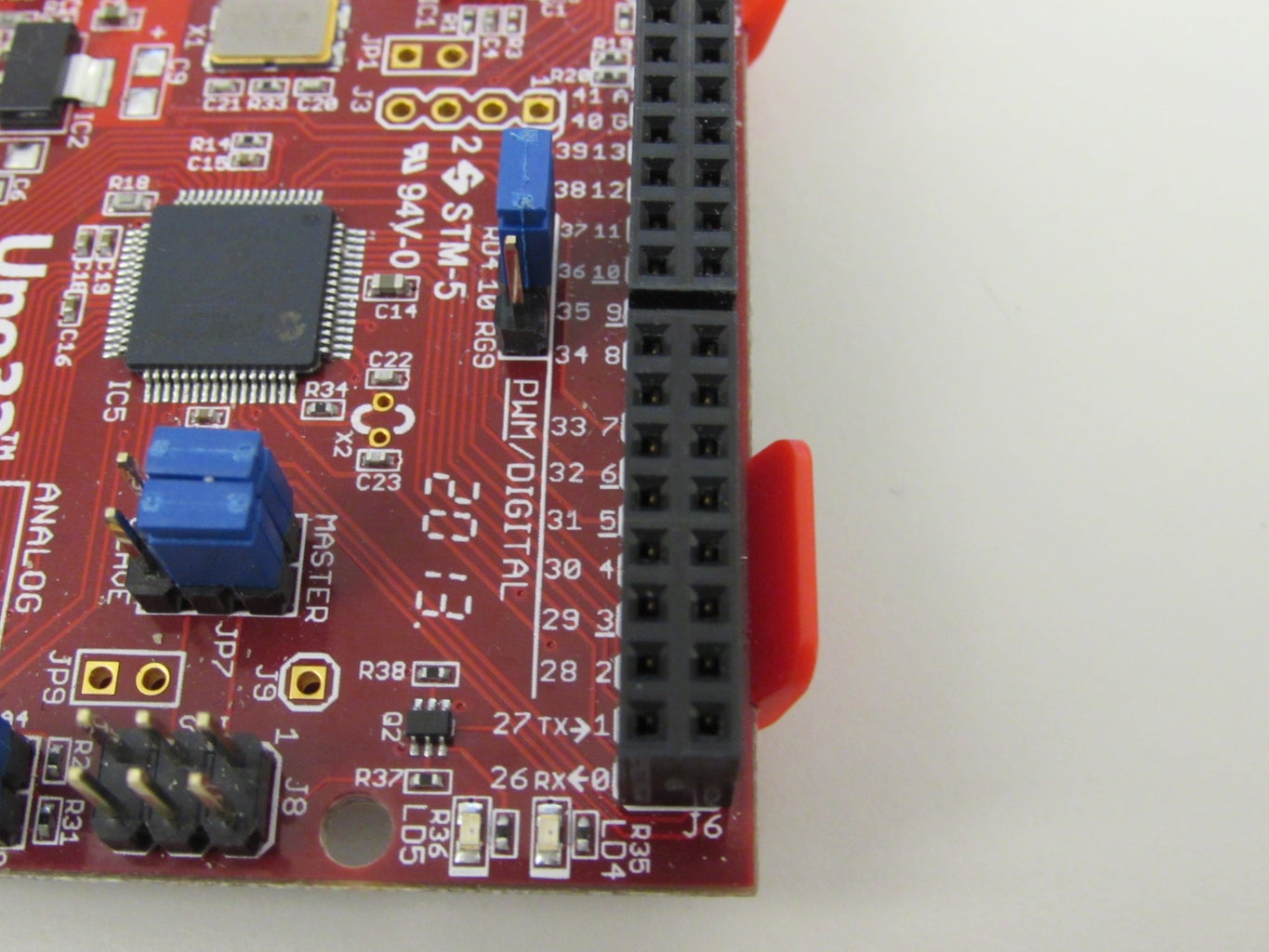

Luckily, the circuit itself is straightforward. The only thing that we need to make sure of is that we use a pwm capable pin on the Uno32. These pins (3, 5, 6, 9, and 10) are identifiable by the underline that appears beneath the numbers alongside the digital pins.
To set up the circuit shown in the picture above, connect one of the negative power rails to a ground pin on the Uno32. Then connect the cathode of the LED to the negative rail and the anode to somewhere else on the breadboard. Attach one leg of the 220 Ohm resistor to the anode of the LED and run a wire from the other leg to one of these pwm capable pins.
Step 7: The Code
We are finally ready to run our pwm signal! Upload the provided code at the bottom of the page to the Uno32 to get the LED performing as shown in the demonstration video. If you think about it hard enough, you may be able to hear the TARDIS in sync with the LED... :)
Please feel free to comment or ask me any questions you may have!
For anybody interested in what other tutorials Digilent has done, check out Digilent's Learn site!


