

Introduction: How to Wire an Arduino-based 3-axis CNC Machine


I've seen a number of tutorials about how to build the platform for a 3-axis CNC milling machine. I have not seen anyone tackle the tricky subject of the electronics.
Here now is my attempt to do so.
Step 1: Parts
- an arduino. I chose duemilanova. (depends on the board you get)
- 3 stepper motors. I chose NEMA 17s . ($15/ea)
- 3 EasyDrivers from Sparkfun . ($15/ea)
- some Cat5 ($2?)
- a 12V power supply for the steppers ($5?)
- a soldering iron
- some electrical tape
- an optional female plug is not a bad idea (<$1)
TIP: Don't get a 6ft or 10ft Cat5 cable. Buy your cat5 by the foot from any computer or electronics store. That stuff has one wire inside instead of lots of little fibers. Little fibers are a huge pain to work with.
Step 2: Wire the Stepper Motor to the EasyDriver

Remove some of the interior wire from the Cat5 and strip the ends. For each servo you will need two normal pairs of white/colored and one oddball of a white and two colored. In all, you'll have to strip 14 ends.
PCB soldering is easy, once you get used to it. There are many other tutorials that cover the subjct. Follow the image as indicated. Your color combinations for the servo may be different. I had to google for a long time to find this page with the color codes for my model.
TIP: "Do NOT connect or disconnect a motor while the driver is energized. This will cause permanent damage." -- Sparkfun
Next we'll wire the power sources and the arduino.
Step 3: Soldering and Wiring.
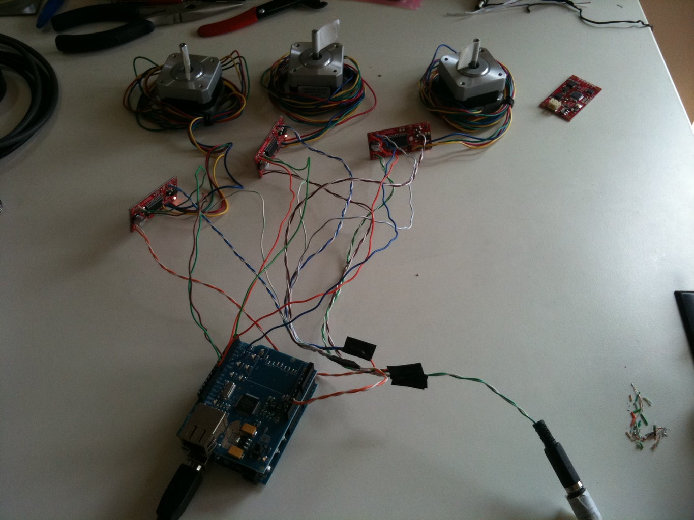
All 3 GND wires from the EasyDrivers are soldered to a single line, which goes to GND on the arduino.
All the positive leads from the stepper power are soldered to a single line.
All the negative leads from the stepper power are soldered to a single line.
TIP: Remember to put the plug cover on the wire BEFORE you solder everything together. Then slide the cover down and over the soldering.
TIP: Don't forget to have everything disconnected while you solder!
Solder the positive and female lines to the female plug.
Double check you didn't wire the board power to the stepper power. That would be bad.
Do you have a multimeter? This would be a good time to check your connections.
Plug in the power. The +5v light in the corner of each board should light up.
Now the wiring is done, time to test it with some code.
Step 4: Testing One Stepper

UPDATE: I've been playing with my steppers and I wrote this little piece of code to play with just a single stepper.
Change the DIR/STEP pins as you see fit. If you put the stepper on a hollow flat surface like a desk top it will sound like a tiny formula 1 race car.
// for duemilanove atmega328 arduino board + easydriver stepper controller
// dan@marginallyclever.com 2010-06-15
#define DIR1_PIN (12)
#define STEP1_PIN (13)
#define DELAY (1600/10)
#define BAUD (9600)
void setup() {
Serial.begin(BAUD);
pinMode(DIR1_PIN,OUTPUT);
pinMode(STEP1_PIN,OUTPUT);
}
void loop() {
int i,j=DELAY;
digitalWrite(DIR1_PIN, LOW); // Set the direction.
delayMicroseconds(DELAY);
Serial.println(">>");
for (i = 0; i<4000; i++) // Iterate for 4000 microsteps.
{
digitalWrite(STEP1_PIN, LOW); // This LOW to HIGH change is what creates the
digitalWrite(STEP1_PIN, HIGH); // "Rising Edge" so the easydriver knows to when to step.
delayMicroseconds(j); // This delay time is close to top speed for this
j+=1;
} // particular motor. Any faster the motor stalls.
digitalWrite(DIR1_PIN, HIGH); // Change direction.
delayMicroseconds(DELAY);
Serial.println("<<");
for (i = 0; i<4000; i++) // Iterate for 4000 microsteps
{
digitalWrite(STEP1_PIN, LOW); // This LOW to HIGH change is what creates the
digitalWrite(STEP1_PIN, HIGH); // "Rising Edge" so the easydriver knows to when to step.
delayMicroseconds(j); // This delay time is close to top speed for this
j-=1;
} // particular motor. Any faster the motor stalls.
}
Step 5: Sample Arduino Code
// for duemilanove atmega328 arduino board + easydriver stepper controller
// dan@marginallyclever.com 2010-06-15
#define DIR1_PIN 4
#define STEP1_PIN 5
#define DIR2_PIN 6
#define STEP2_PIN 7
#define DIR3_PIN 8
#define STEP3_PIN 9
#define DELAY 150
void setup() {
Serial.begin(9600);
pinMode(DIR1_PIN,OUTPUT);
pinMode(STEP1_PIN,OUTPUT);
pinMode(DIR2_PIN,OUTPUT);
pinMode(STEP2_PIN,OUTPUT);
pinMode(DIR3_PIN,OUTPUT);
pinMode(STEP3_PIN,OUTPUT);
}
void loop() {
int i;
digitalWrite(DIR1_PIN, LOW); // Set the direction.
digitalWrite(DIR2_PIN, LOW); // Set the direction.
digitalWrite(DIR3_PIN, LOW); // Set the direction.
delay(DELAY);
Serial.println(">>");
for (i = 0; i<6800; i++) // Iterate for 4000 microsteps.
{
digitalWrite(STEP1_PIN, LOW); // This LOW to HIGH change is what creates the
digitalWrite(STEP1_PIN, HIGH); // "Rising Edge" so the easydriver knows to when to step.
if((i%2)==0) {
digitalWrite(STEP2_PIN, LOW); // This LOW to HIGH change is what creates the
digitalWrite(STEP2_PIN, HIGH); // "Rising Edge" so the easydriver knows to when to step.
}
if((i%4)==0) {
digitalWrite(STEP3_PIN, LOW); // This LOW to HIGH change is what creates the
digitalWrite(STEP3_PIN, HIGH); // "Rising Edge" so the easydriver knows to when to step.
}
delayMicroseconds(DELAY); // This delay time is close to top speed for this
} // particular motor. Any faster the motor stalls.
digitalWrite(DIR1_PIN, HIGH); // Change direction.
digitalWrite(DIR2_PIN, HIGH); // Change direction.
digitalWrite(DIR3_PIN, HIGH); // Change direction.
delay(DELAY);
Serial.println("<<");
for (i = 0; i<6800; i++) // Iterate for 4000 microsteps
{
digitalWrite(STEP1_PIN, LOW); // This LOW to HIGH change is what creates the
digitalWrite(STEP1_PIN, HIGH); // "Rising Edge" so the easydriver knows to when to step.
if((i%2)==0) {
digitalWrite(STEP2_PIN, LOW); // This LOW to HIGH change is what creates the
digitalWrite(STEP2_PIN, HIGH); // "Rising Edge" so the easydriver knows to when to step.
}
if((i%4)==0) {
digitalWrite(STEP3_PIN, LOW); // This LOW to HIGH change is what creates the
digitalWrite(STEP3_PIN, HIGH); // "Rising Edge" so the easydriver knows to when to step.
}
delayMicroseconds(DELAY); // This delay time is close to top speed for this
} // particular motor. Any faster the motor stalls.
}
Step 6: In Conclusion

If everything worked right, you should have three steppers each moving at different speeds back and forth. There should be a light on each EasyDriver showing that it has power. If you have a light and no movement, You might not have a good connection to your arduino.
So what next?
Now that you have three motors working through the arduino you can use the serial interface to tell the arduino what you want the steppers to do. By changing the different motors in the right pattern you can interpret G-CODE and start cutting patterns. The biggest choice you face is what to cut!
Thanks for reading!
Dan


