

Introduction: IR Remote Control Switch


This project describes a technique of adding the remote control feature to an electrical appliance. The goal is to construct a black box where you can plug in your V Ac appliances and control the ON and OFF operations with a TV or DVD remote that uses modulated infra-red (IR) pulse train of 38KHz frequency. The good thing about this project is that it does not use any microcontroller and is only based on the CD4017 decade counter IC.
Step 1: Circuit Diagram:


The circuit diagram below is mostly the same. It uses a TSOP1738 IR receiver module at the input side to receive the 38 KHz frequency IR pulses from the remote control. Under normal condition, the output pin of the IR module is at logic High, which means the transistor T1 (BC558 PNP) is cut-off and its collector terminal is at logic Low. The collector of T1 drives the clock line of the CD4017 decade counter.
This is how it's look on breadboard. I insist you all to test the circuit on breadboard first.
Step 2: Part List:


Components:-
- IC: CD4017
- TSOP 1738 (IR receiver)
- Resistors: 10k x 3, 1k, 100 ohms,100k
- Capacitors: 10uf x 2
- Transistors: BC558 (PNP) and BC548 (NPN)
- 5Volt relay
- Diodes: 1N4001
- Led: red or any other x 2
- Wires
- Bread Board - 1 nos
- Prototyping PCB board - 1 nos
- 5V Power Source
- 220V home appliances
Tools required:
- Soldering Iron
- Wirecutter
- Soldering Lead
Step 3: Operation:

The circuit uses a TSOP 1738 IR receiver module at the input side to receive the 38KHz frequency IR pulses from the remote control. Under normal condition, the output pin of the IR module is at logic High, which means the transistor T1 (BC558 PNP) is cut-off and its collector terminal is at logic Low. The collector of T1 drives the clock line of the CD40174 decade counter. When you face a remote towards the TSOP and press any key. Then The TSOP module receives the train of 38KHz IR pulses from the remote that makes its output to oscillate too. These pulses are inverted at the collector of BC558, which finally go to the clock input of the decade counter. The arriving pulses could increment the CD4017 counter at the same rate (38KHz), but because of the presence of the RC filter circuit (R=100K, C=10uf) between the collector and the ground, the train of pulses appear as a single pulse to the counter. Thus, on each key pressing the CD4017 counter advances only by a single count. When the user releases the key , the C1 capacitor discharges through the R1 resistor, and the clock line is back to zero. So every time the user presses and releases a key on the remote, the CD4017 counter receives a single pulse at its clock input.
Step 4: Brief:-

Initially , when the circuit is just powered on, the Q0 output of CD4017 decade counter goes high. The counter increments for each low-to-high going pulse arriving at its CLK pin (14). When the first pulse arrives , Q0 goes Low and Q1 is turned high. This activates the relay and the AC appliances connected to it is turned on . The status LED also glows to indicate the appliance is switched on. When the user presses a key again, the second pulse arriving at the CLK line increments the counter by 1. Since Q2 is wired to the Reset input , the second key press actually brings the CD4017 IC back to the power-on-reset conditions with Q0 High. Thus, it simply operates as an ON/OFF toggle switch controlled with any key of an infrared remote.
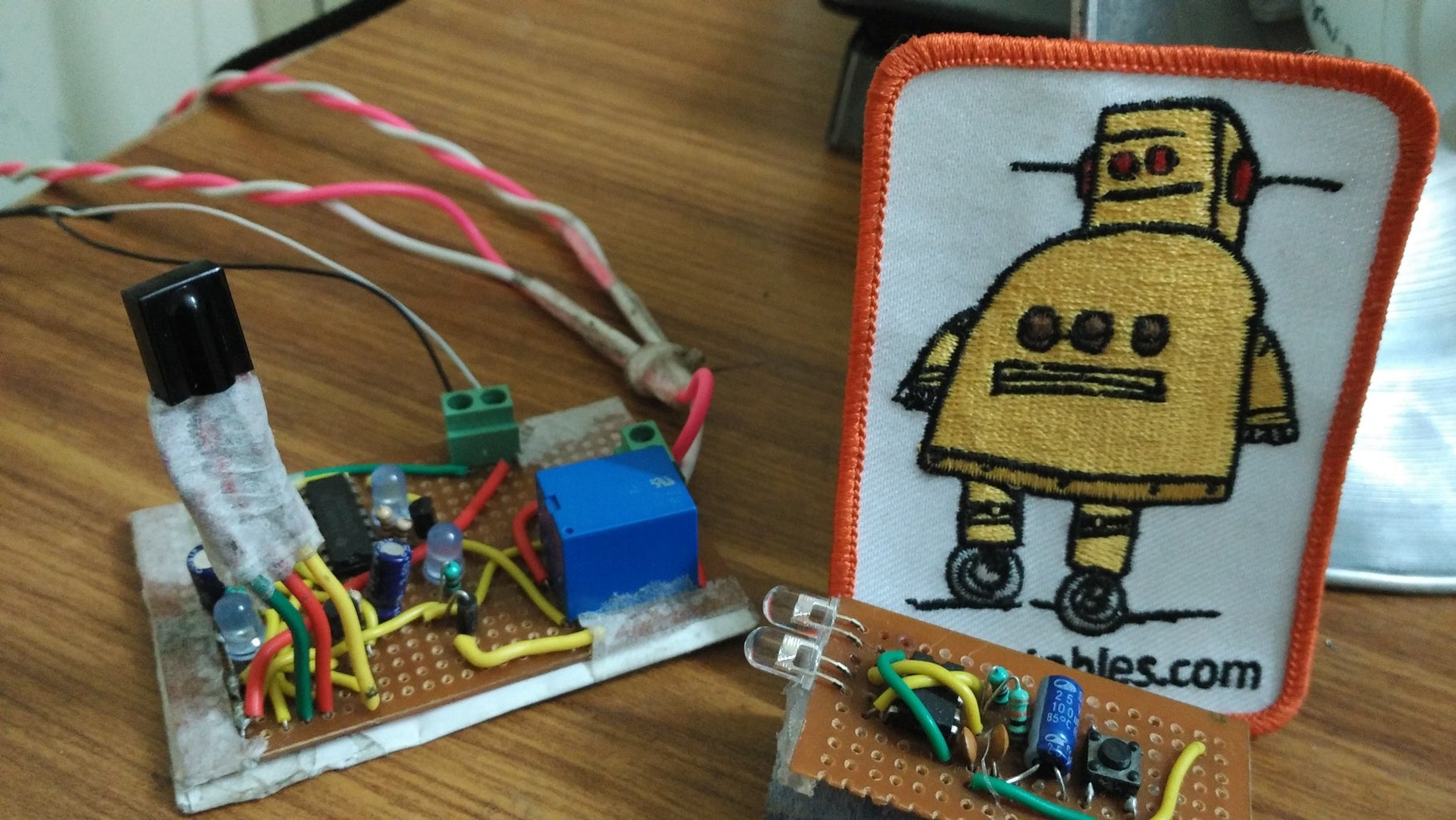
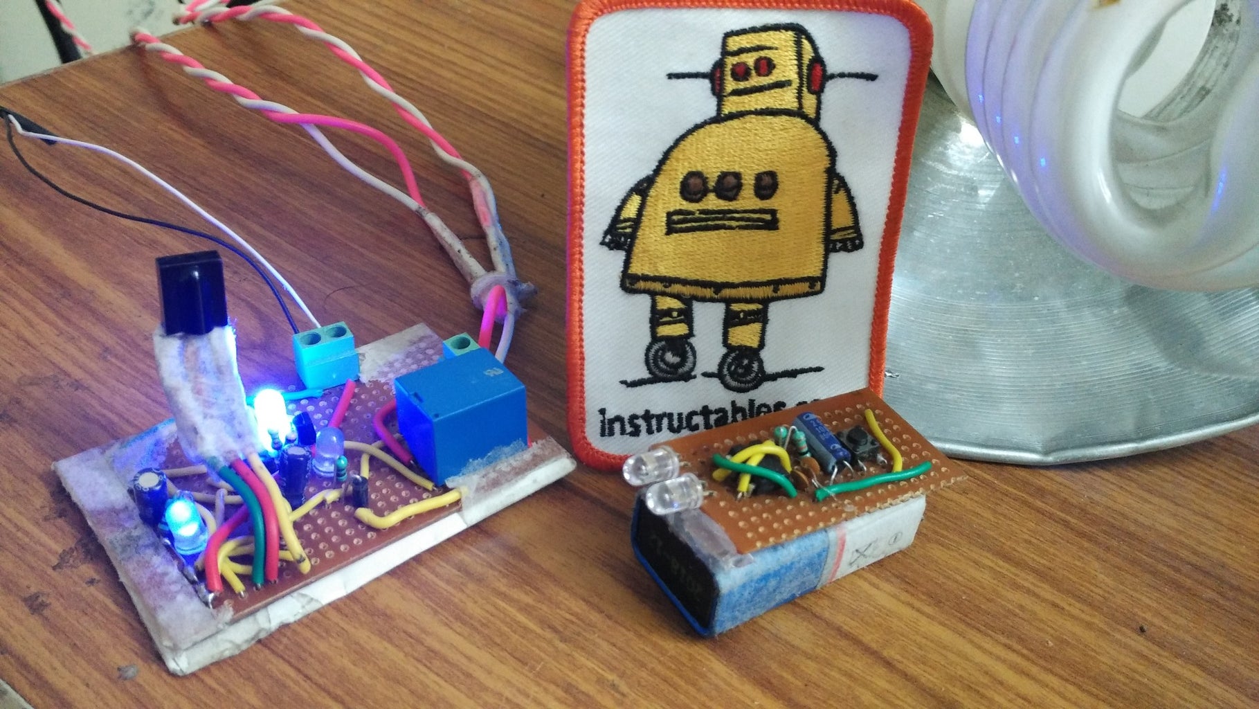
Step 5: Added Extra LED


Here I added extra 1 LED which is indicating that the Power of 220V is Off. When I press the key of my remote then the extra LED will switched off and the 3 LED which is in our circuit diagram will glows up.
1st LED is always blinking is is the indication of receiving the 38KHz frequency IR pulses. It will blink all time because Infrared Frequency is everywhere.
2nd LED is showing that the Power of 220V is Off. this is the extra LED in this circuit. If you want to know where to put the extra LED in the circuit the see the bread board pic carefully otherwise please comment I will tell you.
And the 3rd LED is showing that the Power of 220V is On.
Step 6: IR Remote

I will upload the new Instructables for IR remote in some days.
For now this is it.
And don't forget to vote me if you like this.
Step 7: What Next
Next:- HAND MADE IR REMOTE

Participated in the
Full Spectrum Laser Contest 2016

Participated in the
Digital Life 101 Challenge


