

Introduction: Implementing Christopher Kitrick's "Nine Methods for a Right Spherical Triangle" in Autodesk Inventor


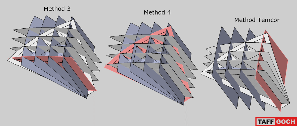
In my Temcor tutorial, I showed how to construct a Temcor-style geodesic dome using only a bit of math. After than, I continued reading more on class II methods, and eventually stumbled upon this Google Groups thread, where Taff Goch discovered that Duncan Stuart's "Method 3" relies on a Right Spherical Triangle, instead of a planar right triangle, as in methods 1 and 2 for Class I and II geodesic spheres. I quickly went to work constructing a catalog of Method 3 spheres up to 16V, but then ran across Christopher Kitrick's A Unified Approach to Class I, II & III Geodesic Domes, and tried my hand at reproducing his "Method 4 (Method cb)" outlined in the paper to construct the 8V sphere in his 1985 paper Geodesic Domes.
I was having trouble in my first few attempts, but, after going over Taff Goch's diagram, I decided to construct the parallel planes first, then had an idea: Create intersection curves using the parallel planes, create planes normal to the intersection curves, generate intersection curves from those planes, then form the subdivision. Result: Perfect reproduction of the spherical angles listed in Geodesic Domes. I could now say in confidence that the dashed lines in figures 13-21 in his 1990 paper represent parallel planes, and the solid lines represent radially copied planes. From this, all the other methods can be reproduced.
For this tutorial an 8V Class II sphere will be constructed using the 9 methods outlined in the 1990 paper.
Step 1: Getting Familiar With the Spherical Triangle and a Note on Parallel Vs. Radial Planes


I've prepared a template for constructing each of the 9 methods, which can be downloaded at the end of this step. The sides are marked in the first image, except Side 'a', which is the YZ plane. In the second image, I've created 2 work planes, one on the endpoint of the orange line which is parallel to Side 'b', the other rotated about the orange line and perpendicular to the YZ plane. The red arc is from the parallel plane (blue side facing towards you), while the yellow arc is from the plane rotated about the orange line (orange side facing towards you). In the third image, the difference between the arcs can be more clearly seen.
The methods are named in two or three parts: The chosen side to uniformly divide into the desired frequency, which leg of the spherical triangle has perpendcular arcs intersecting it, and, optionally, perpendicular arcs intersecting another leg of the spherical triangle. So, for Method 'bba', Side 'b' is divided into equal angles, and perpendicular arcs intersect both sides 'b' and 'a'.
In the last image, I've added the equations for the three central angles of the sides of the triangle - you can ignore them and use the vertices of the spherical triangle, but I prefer to use the equations to make my model a little more robust against future changes to the part.
Now that the difference has been illustrated, it's time to start with the first method - Method 'aa'.
Attachments

Step 2: Method 'aa': 'Temcor' Method for Geodesic Spheres


This method is essentially Temcor's method, but without the radial patterning of the outer triangles of one half of the subdivision across Side 'a', and without the truncation of the bottom rows in the linked image. For this method, I've outlined every single step in constructing the sphere. For the later methods, only a subset of the steps will be shown, and the instructions on how to replicate them will be provided in the images.
-----------------------
Subdivision Data:
Chord Factors:8
0.14070446959688 | 0.1579025609629 | 0.16499817827254 | 0.17231757860862
0.17380034890599 | 0.17995311550259 | 0.18069206748981 | 0.18217903636038
Longest chord/shortest chord (L/S Ratio): 1.2947636765365
Step 3: Method 'ab'


-----------------------
Subdivision Data:
Chord Factors:11
0.15544092377983 | 0.15801384020282 | 0.15890059854444 | 0.16377479918291
0.16570311930677 | 0.16667499438189 | 0.17440143608169 | 0.17770945181873
0.1799425999955 | 0.18106745457301 | 0.18217903636038
L/S Ratio:
1.1720146273604
Step 4: Method 'aab'


-----------------------
Subdivision Data:
Chord Factors:13
0.14070446959688 | 0.15383168140065 | 0.1579025609629 | 0.16499817827254
0.16780137349359 | 0.17186889388239 | 0.17231757860862 | 0.17373454517661
0.17980069838471 | 0.17995436921097 | 0.18069206748981 | 0.18217903636038
0.18524560549768
L/S Ratio:
1.2947636765365
Step 5: Method 'ba'


-----------------------
Subdivision Data:
Chord Factors:14
0.15980447027924 | 0.16087773483718 | 0.16170683204053 | 0.1645712080359
0.1651694636463 | 0.16614383209276 | 0.16767389466201 | 0.17114603321549
0.17357655996231 | 0.17482656244546 | 0.17490795862366 | 0.19641854771476
0.19977263726999 | 0.21260255227239
L/S Ratio:
1.3303917712746
Step 6: Method 'bb' (Duncan Stuart's 'Method 3')


-----------------------
Subdivision Data:
Chord Factors:8
0.15331576153274 | 0.16102639307746 | 0.16700322284542 | 0.16867215218162
0.17028662066488 | 0.18491392129355 | 0.19567754711714 | 0.1994570037297
L/S Ratio:
1.300955633887
Step 7: Method 'bba'


-----------------------
Subdivision Data:
Chord Factors:14
0.15331576153274 | 0.15689500368701 | 0.16102639307746 | 0.16115148445783
0.16239749248308 | 0.16651289750502 | 0.16700322284542 | 0.17028662066488
0.17514890187365 | 0.17677805513362 |0.19567754711714 | 0.1994570037297
0.20318630081948 | 0.21570738993446
L/S Ratio:
1.4069485601348
Step 8: Method 'ca'


-----------------------
Subdivision Data:
Chord Factors:12
0.16290884971854 | 0.16461054221798 | 0.16660044354274 | 0.16734916348945
0.16841250198965 | 0.16917133930661 | 0.17323352662764 | 0.17524002095434
0.17609646074706 | 0.18926198471317 | 0.19087446105494 | 0.20689026976643
L/S Ratio:
1.2699756343739
Step 9: Method 'cb' (Kitrick's 'Method 4')


-----------------------
Subdivision Data:
Chord Factors:11
0.16290884971854 | 0.1648712218293 | 0.16684013263025 | 0.1687698457052
0.16882677179713 | 0.17276884604382 | 0.17479305838157 | 0.17516583201886
0.18404408843203 | 0.18918998255912 | 0.19087446105494
L/S Ratio 1.1716641630256
Step 10: Method 'cab'


For this last method, there are two ways to get the correct perpendicular arcs; project the points coincident with Side 'c' to sketches on Side 'b' and the YZ plane, or, as shown here, using parallel arcs.
-----------------------
Subdivision Data:
Chord Factors:13
0.16244617338947 | 0.16290884971854 | 0.16461054221798 | 0.1648712218293
0.16734916348945 | 0.17255753256904 | 0.17341341421338 | 0.17610321403293
0.17922252723077 | 0.18918998255912 | 0.19087446105494 | 0.19699881572298
0.20674196435151
L/S Ratio:
1.2726798054876
Step 11: Method References
Here is a full list of the authors Kitrick cited in A Unified Approach to Class I, II & III Geodesic Domes:
Referenced by the paper:
-----------------------
1. COXETER, H.S.M., "Virus Macromolecules and
Geodesic Domes", A Spectrum of Mathematics, ed. J.C.
Butcher, Auckland University Press and Oxford
University Press, 1972, pp. 98-107.
2. WENNINGER, M. J., Spherical Models, Cambridge
University Press, 1979, p. 98-100, 120-121.
4. TARNAI, T., "Geodesic Domes with Skew Networks",
Spherical Grid Structures, ed. T. Tarnai, Hungarian
Institute for Building Science, 1987.
5. MAKAI, E., "On Polyhedra with Approximately Equal
Edges", Spherical Grid Structures, ed. T. Tarnai,
Hungarian Institute for Building Science, 1987.
7. GOLDBERG, M., "A Class of Multi-Symmetric
Polyhedra", Tohoku Mathematical Journal, 43, Tokyo,
Japan, 1937, pp. 104-108.
8. MAKAI, E., and TARNAI, T., "Uniformity of Networks
of Geodesic Domes", Spherical Grid Structures, ed. T.
Tarnai, 1987, Hungarian Instinrte for Building Science.
Cited in "Table 7 - Cross Reference":
*3. KITRICK, C.J., "Geodesic Domes", Structural Topology,
University of Montreal, 11, 1985, pp. 15-20.
*6. CLINTON, J.D., Advanced Structural Geometry Studies,
Part I, Polyhedral Subdivision Concepts for Structural
Applications, NASA CR-1734, Sept. 1971.
9. SCHEEL, H., "Geodesic Surface Division", The Cana-
dian Architect, 14, No. 5, 1969, pp. 61-66.
10. STUART, D.R., A Report on the Triacon Gridding Sys-
tem for Spherical Surface, Skybreak Carolina Corpora-
tion, 1952.
11. TARNAI, T., "Spherical Grids of Triangular Network",
Acta Technica Acad. Sci. Hungar., 76, 1974, pp. 307 -
336.
12. PAVLOV, G.N., "Compositional Form-shaping of
Crystal Domes and Shells", Spherical Grid Structures, ed.
T. Tarnai, 1987, Hungarian Institute for Building Science.
*Clinton's Paper describes "Method 6", which is nowadays called "Class II Method 3", or, in Kitrick's 1990 paper, Method 'bb'. "Method 7" in Clinton's paper is also called "Method 4" in Jay Salsburg's paper, "Geodesic Math", and Method 'cb' in Kitrick's 1990 paper. In Geodesic Domes, Kitrick notes that the L/S Ratio of 'Method 7/Method 4/Method cb' is always near or below the limit of 2sin(36°) for any frequency.


