

Introduction: Improvements to My Lathe Headstock.


For some time I have been planning to change the single phase, single speed motor on my lathe for a larger 3 phase motor driven by a VFD (Variable Frequency Drive). The infinitely variable motor speed would allow me to eliminate the multiple pulley speed change system, but there is a problem when running a motor at low speed with a VFD. For a given spindle speed the spindle torque from a motor running at slow speed is less than achieving the same slow speed by mechanical gearing, for a given motor. A way around this problem is to use a vastly oversize motor.
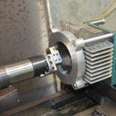
It also helps if you use a two speed motor, for example a 2/4 pole or a 4/8 pole motor. I was lucky enough to find on an auction site the 4/8 pole 5.5 hp motor pictured below. Fed with 50 Hz supply that gives speeds of nearly 1500 and 750 rpm. The slower speed range will give approximately double the motor torque. Thus such a motor will give me a wider useful speed range. I almost never need to run at very low speeds anyway.
This document is not about fitting the motor but is about some changes to the lathe head that the motor allowed me to do. The most important was to stiffen the head assembly to reduce any tendency to chatter and provide a better platform to get good surface finish and accuracy. Although I show how I did this on my lathe, a 1240 JET, the ideas are certainly applicable to many other types of lathe especially lathes which do not have a closed in spindle head. The selection of materials will depend on the details of the lathe being worked on.
Step 1: Tools and Materials

Materials
- Lathe. This is in Materials because it is the focus of the post but is not used as a tool in the project.
- Miscellaneous bolts.
- Cement, sand and gravel to make some concrete.
- Aluminium to make a magnet holder for a spindle tachometer.
- Tachometer kit, there are many low cost options on the internet.
- Steel plate.
Tools
- Milling machine.
- Drill bits and thread taps.
- Container and trowels to mix concrete.
- Spanners, allen keys and/or torx wrenches to suit the bolts being used.
Step 2: Drive System


The original drive system had a counter shaft inside the head at the rear which was driven by a vertical V-belt from the motor and which drove the spindle by a horizontal V-belt.
I planned on using a single poly-V belt fitted externally. I prefer poly-V belts, their thin section enables them to bend easier over the pulleys than traditional V-belts and generally cause less vibration. They also have a large torque capacity.
Step 3: Gutting the Original Drive System


With the drive now on the outside all of the old drive system could be removed from inside leaving only the main spindle.
The above photos show the head in progressive states of dismantling. It can be seen clearly that the rearward open section of the head was there solely to support the drive mechanism, it adds virtually noting to the stiffness of the head. Shaped as it is there is a lateral mode of vibration which if excited could be the cause of chatter. I thought that just cutting that section off could only be an improvement. Further improvement to head stiffness would come by closing in the open rear and top sides after removing the rear section.
Step 4: The Plan


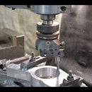
The plan was to cut the rear part of the head off in the milling machine. Initially I planned to cut along a vertical line as described in the next step, but as soon as that was done I realised that it would be better for rigidity to cut on an angle as shown above right up next to the bearing supports.
Step 5: The First Cut Is the Deepest


The first photo shows the initial vertical cut, and the second shows the reduced head test fitted back on the lathe.
Step 6: The Second Cut Is the Best


The first two photos show the head clamped to the mill table for the final machining of the rear surface up close to the bearing housings. The top piece (see next step) was bolted in place as that would be part of the surface for the rear plate.
The remaining photo shows a test fitting on the lathe with both top and rear plates in place.
Step 7: The Top Bracing Plate


The top cover was made by cutting a piece off the removed rear section, cast iron has greater damping than steel and is to be preferred. This had a thick piece at what was the original rear corner, I kept that and milled it to be a size for size fitting into the main section of the head where I had milled parallel surfaces. This top cover was drilled and tapped and bolted in place laterally. This ties the “unsupported” corners of the bearing housings tightly together and that alone probably provides most of any added stiffness. The top plate is also bolted vertically along the front and sides. The rear plate was made from some 6 mm steel plate, that was both bolted and glued in place, I had no more suitable pieces of cast iron. I now consider this rear piece to be permanently attached to the head never to be removed. The top is removable to aid changing bearing seals.
Step 8: Rear Plate


The rear plate is extended upward and has two tabs welded at the top. This is to mount the original hinged lid for somewhere to put micrometers, calipers and small work pieces. It will be fixed in place not hinged. The original was hinged to allow for speed change by changing pulleys. These two photos show the assembly after the rear plate had been glued and bolted permanently.
Step 9: Mounting a Spindle Tachometer Pickup.


Without the internal drive system there was plenty of space to mount the pickup for a spindle tacho out of harm’s way. I made an aluminium ring with a slight interference fit on the spindle and drilled a hole to glue in place the magnet for the tacho. On the rear face of the ring I drilled another but deeper hole. This was to remove some metal to balance the extra mass of the magnet compared to the aluminium. Maybe over the top but ……...
A tachometer is an important addition to a lathe or milling machine that is driven by a variable speed motor/VFD combination.
Step 10: Putting Things in Concrete Form


The final piece of the puzzle will come as a surprise to most readers, but what do you expect from a thug who inflicts GBH on a lathe? The spindle is wrapped in plastic to keep it clean while I shovelled in concrete to just under the bearing seals. There are three factors which control vibration in physical systems, which means chatter and/or poor surface finish when applied to a lathe. These are mass, stiffness and damping. I attended to the stiffness by the addition of the top and rear covers. Concrete adds both mass and damping to the assembly.
Lead would be the best material but perhaps excessive. Molten lead of the necessary volume might well heat the seals beyond sensible limits and/or cause the iron casting to crack due to the sudden and uneven heating. Pre-heating the head might help avoid cracking but would make the seal heating problem worse.
On a more practical level “epoxy-granite” would be a good choice for the filling in place of concrete. Epoxy-granite is a mixture of granite gravel (or similar material) bound together in a matrix of epoxy. It is becoming a popular material for the construction of one off special purpose machine tools in place of cast iron. Cast iron is cheap in quantity but expensive for one offs. A steel framework can be cast inside an epoxy-granite machine tool frame for added stiffness.
I will leave the top cover off until the concrete has set and dried thoroughly. If it were covered too soon then condensation may occur on the spindle. The drying may take up to two weeks or so. When it has dried out I will pour a thin layer of old paint over the concrete to seal it and prevent any dust.
Step 11: Time Will Tell


Time will tell whether my efforts were worth it. It looks like a lot of work but in truth it did not take very long. The machining was pretty straight forward milling work with fairly simple setups. In any case I had wanted to replace seals and examine the bearings which was probably the most time consuming part.
At this point all I can say is that the lathe runs quieter and smoother than before, but there is no doubt that this is due to the much simpler drive system, smoothness usually translates into better surface finish.
I intend to put together a Youtube video but in the meantime here is a 2 minute video showing some stiffness measurements. Stiffness tests
Tony Foale June 2019
You can visit my web site at Tony's web site
My Youtube channel has several more examples of tools and test equipment that I have made and can be found here Tony's Youtube please like, share and subscribe to my channel if you find the content of interest.


