

Introduction: Infinity Mirror Clock

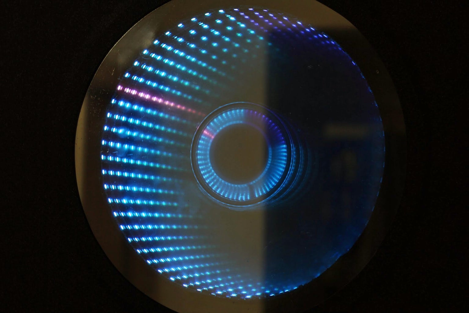


Ever since my addressable RGB LED strips (WS2812B) came from Aliexpress, I've been fascinated with LED projects. Following up on my success with my Charlieplexed LED clock, I wanted to create something with more Jazz..
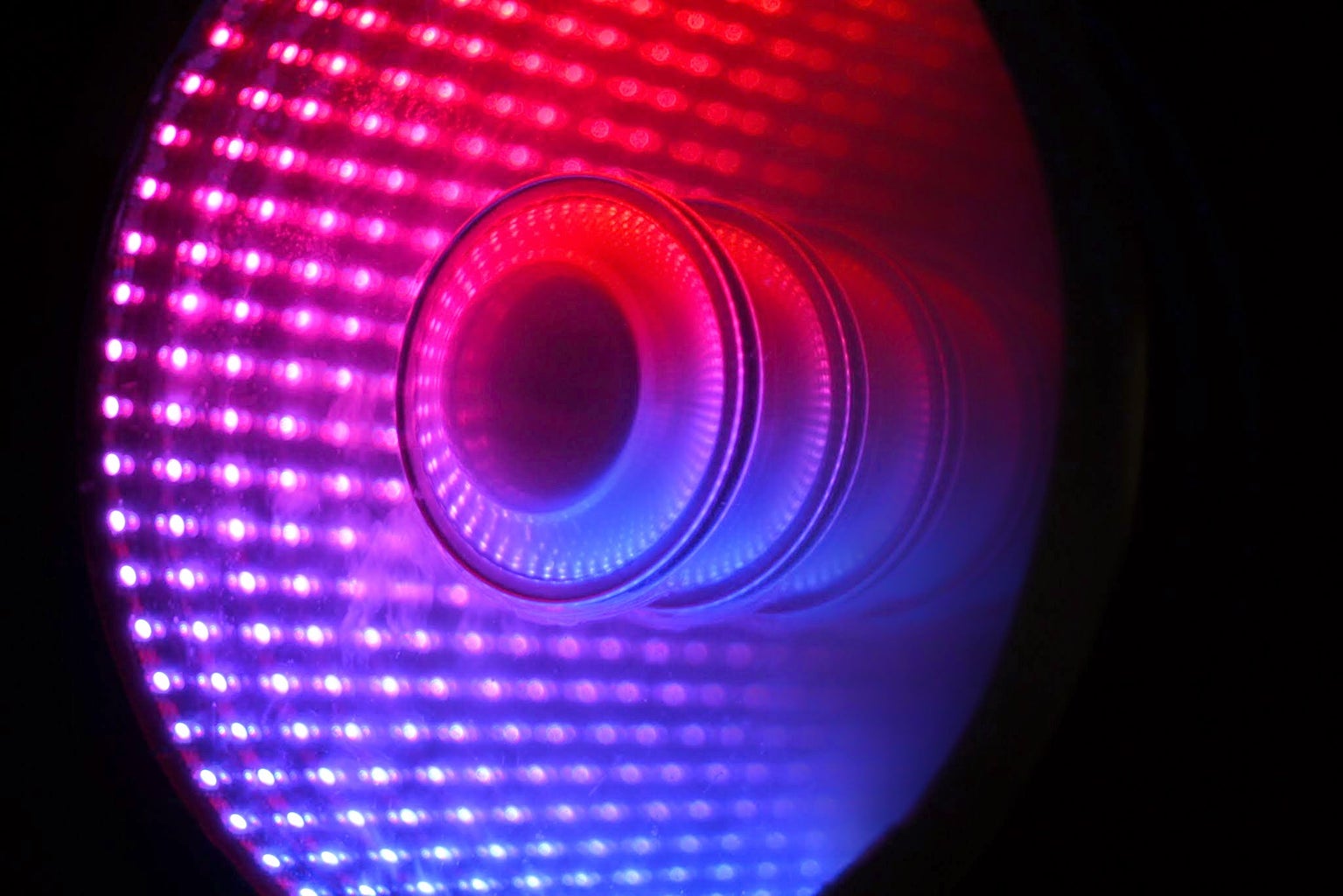
While browsing google images, I came across an instructable for an Arduino Infinity Mirror and the brain cells started working in overdrive. Why shouldn't I make an infinity mirror, that's also a clock !!
Features:
- Works like a clock - the colours of the hands are user-programmable over bluetooth
- Has an IR sensor to sense if someone is coming near the mirror. Switches off the LEDs, so that this can be used as a normal mirror :-)
- Shows a rainbow effect every 15 minutes (time is user adjustable)
- Has a touch button to toggle between clock and rainbow effects
- Switches to night mode between midnight and 7:00 AM - can be changed in the code.
- Can be programmed over bluetooth - so you do not need to take it off the wall if you need to update the code

Step 1: Electronics
- A Standalone Arduino: http://dushyant.ahuja.ws/2013/10/standalone-arduin... OR Arduino mini pro: http://www.aliexpress.com/item/10Pcs-Lot-Pro-Mini-...
- RTC Module – DS1302: http://fabtolab.com/DS1302-RTC-module?search=rtc
- LM2596 Step Down Adjustable Power Supply Module 1.3V-35V: http://cgi.ebay.in/ws/eBayISAPI.dll?ViewItem&item=...
- 1m 60LEDs/M Addressable RGB LED Strip (WS2812B): http://www.aliexpress.com/item/1M-WS2812-WS2812B-6...
- HC-05 Bluetooth module: http://www.aliexpress.com/item/RS232-TTL-LC-05-Wir...
- IR Proximity Sensor: https://www.instructables.com/id/Simple-IR-proximit...4 IR LEDs; 1 IR LED detector: http://www.evelta.com/industrial-control/sensors/5...
- Touch Pad: http://www.aliexpress.com/item/Touch-Pad-Brick-Sen...
- 9V – 2A Adapter
- CP2102 USB-to-TTL (the RST pin on the CP2102 is not for resetting the arduino – you have to solder a wire to the DTR pad on the PCB – which sends a reset signal to program the arduino. This has to be connected to the DTR pin on the Arduino
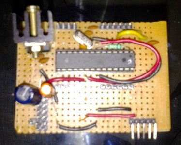
Step 2: The Circuit

The circuit is very simple:
- LED Strip - Connect power to the LM2596 Step Down Adjustable Power Supply Module - ensure you adjust the pot so that the output is 5V; Connect the ground to the common ground; Connect data to pin D5 of the Arduino
- Touch Sensor - data to pin D2 of Arduino
- RTC Module - SDA and SCL to the A4 and A5 of the Arduino respectively
- Bluetooth Module - Connect RX to Arduino's TX and TX to Arduino's RX. You will have to break-out pin 32 on the module to the DTR pin on the Arduino (This allows you to program the Arduino over bluetooth)
- IR Proximity Sensor - create the sensor as per this instructable: https://www.instructables.com/id/Simple-IR-proximit... - connect the photo-diode to A1 (A0 on the instructable schematic) and the IR LEDs to D13 (D2 on the instructable schematic)
- Connect the Power 9V 2A Power supply to the input of the 7805 and the LM2596
To setup the bluetooth programming circuit, please follow this link: http://makezine.com/projects/diy-arduino-bluetooth...
Attachments

Step 3: The Code
This clock uses the following libraries (and all thanks to the authors of these libraries):
- RTCLib Arduino Library: https://github.com/adafruit/RTClib
- FastLED Arduino Library v2.1: http://fastled.io/https://github.com/FastLED/FastLED/releases/tag/ar... (have linked to the v2.1 of the library as I'm not sure if any code changes are required to support v3.0)
- SerialCommand Arduino Library: https://github.com/scogswell/ArduinoSerialCommand...
- TimerOne Arduino Library: https://code.google.com/p/arduino-timerone/
The latest version of the code can be downloaded from the project github: https://github.com/dushyantahuja/Smart-Infinity-Mi...
#include <Wire.h>
#include "RTClib.h"
#include "FastLED.h"
#include <SoftwareSerial.h>
#include <SerialCommand.h>
#include "EEPROM.h"
#include "TimerOne.h"

#define NUM_LEDS 60
#define DATA_PIN 5
#define UPDATES_PER_SECOND 100
#define SWITCHPIN 2

// Variables for IR Proximity

int IRpin = A1;               // IR photodiode on analog pin A1
int IRemitter = 13;            // IR emitter LED on digital pin 4

//

CRGBPalette16 currentPalette;
TBlendType    currentBlending;

CRGB leds[NUM_LEDS],minutes,hours,seconds,l,bg,lines;
RTC_DS1307 rtc;
SerialCommand sCmd;
boolean missed=0, ledState = 1, lastsec=1, multieffects = 0;
byte lastsecond, rain;
int light_low, light_high;
DateTime now;

void(* resetFunc) (void) = 0;

void setup() {
  digitalWrite(IRemitter,LOW);             // turning the IR LEDs off - as a precaution - they don't have current limiting resistors
  Wire.begin();
  rtc.begin();
  Serial.begin(115200);
  FastLED.addLeds<WS2812B, DATA_PIN, GRB>(leds, NUM_LEDS);
  currentPalette = RainbowStripeColors_p;
  currentBlending = NOBLEND;

  // ******** Setup the default values for parameters (if not set before)
  if (EEPROM.read(99) != 1){               // Check if colours have been set or not
    EEPROM.write(0,255);                   // Seconds Colour - R-G-B - White
    EEPROM.write(1,255);
    EEPROM.write(2,255);
    EEPROM.write(3,255);                   // Minutes Colour - R-G-B - Red
    EEPROM.write(4,0);
    EEPROM.write(5,0);
    EEPROM.write(6,0);                     // Hours Colour - R-G-B - Green
    EEPROM.write(7,255);
    EEPROM.write(8,0);
    EEPROM.write(9,0);                     // BG Colour - R-G-B - Black
    EEPROM.write(10,0);
    EEPROM.write(11,0);
    EEPROM.write(12, 0);                   // Light sensitivity - low
    EEPROM.write(13, 55);                  // Light sensitivity - high
    EEPROM.write(14, 15);                  // Minutes for each rainbow
    EEPROM.write(99,1);
  }
  // Else read the parameters from the EEPROM
  else {
    seconds.r = EEPROM.read(0);
    seconds.g = EEPROM.read(1);
    seconds.b = EEPROM.read(2);
    minutes.r = EEPROM.read(3);
    minutes.g = EEPROM.read(4);
    minutes.b = EEPROM.read(5);
    hours.r = EEPROM.read(6);
    hours.g = EEPROM.read(7);
    hours.b = EEPROM.read(8);
    bg.r = EEPROM.read(9);
    bg.g = EEPROM.read(10);
    bg.b = EEPROM.read(11);
    light_low = EEPROM.read(12);
    light_high = EEPROM.read(13);
    rain = EEPROM.read(14);
  }

  // ********** Setup the serial commands

  sCmd.addCommand("MULTI", set_multi);
  sCmd.addCommand("STAT", clockstatus);
  sCmd.addCommand("SETRAIN", set_rainbow);
  sCmd.addCommand("HOUR", set_hour);
  sCmd.addCommand("MIN", set_minute);
  sCmd.addCommand("SEC", set_second);
  sCmd.addCommand("BG", set_bg);
  sCmd.addCommand("LIGHT", set_light);
  sCmd.addCommand("TIME", set_time);
  sCmd.addCommand("MISSED", missedCall);
  sCmd.addCommand("MISSEDOFF", missedOff);
  sCmd.addCommand("RAINBOW", effects);
  sCmd.addCommand("MISSED", missedCall);
  sCmd.addCommand("MISSEDOFF", missedOff);
  sCmd.addDefaultHandler(effects);

  // ********** Set all LEDs to background colour
  for (int i = 0; i < NUM_LEDS; i++) {
    leds[i] = bg;
  }

  pinMode(IRemitter,OUTPUT);  // IR emitter LED on digital pin 2
  digitalWrite(IRemitter,LOW);// setup IR LED as off
  clockstatus();
  attachInterrupt(1, set_multi, FALLING);
  Timer1.initialize();
  Timer1.attachInterrupt(state, 500000);
}

void loop() {
  sCmd.readSerial();
  if(readIR(10) > 50){            // Switch off LEDs if someone is near the mirror - so that it can be used as a mirror. Switch off LEDs between 12:00 and 6:00 to save energy and cool down the LEDs and power supplies
    for (int i = 0; i < NUM_LEDS; i++) {
      leds[i] = CRGB::Black;
    }
    FastLED.show();
    ledState = 1;
    //FastLED.delay(200);
  }
  else {
  for (int i = 0; i < NUM_LEDS; i++) {
    leds[i] = bg;
  }
  if(multieffects){                 // Check if the button for multi-effects has been pressed
    uint8_t secondHand;
    secondHand = now.second();
    if( secondHand ==  0)  { currentPalette = RainbowColors_p;         currentBlending = BLEND; }
    if( secondHand == 30)  { currentPalette = RainbowStripeColors_p;   currentBlending = BLEND;  }
    static uint8_t startIndex = 0;
    startIndex = startIndex + 1;
    FillLEDsFromPaletteColors( startIndex);
    FastLED.show();
  }
  else if(ledState){                	// Main clock code
    // Setting brightness to light_high
    int x = light_high; 		// analogRead(IRpin);
    now =  rtc.now();
    if(( now.minute() % rain == 0 && now.second() == 0)){
       effects();
    }
    for(byte i=0; i<=now.minute();i++){
      //Serial.println(minutes);
      leds[i] = minutes;
    }
    //Serial.println(now.hour(),DEC);
    for(byte i = 0; i<60; i+=5){
      leds[i]=CRGB::White;
    }
    for(byte i=(now.hour()%12)*5; i<=((now.hour())%12)*5+(now.minute()/12);i++){
      leds[i] = hours;
    }
    if(now.hour() < 7) LEDS.setBrightness(constrain(light_low,0,100)); 		// Set brightness to light_low during night - cools down LEDs and power supplies.
    else LEDS.setBrightness(constrain(light_high,10,255));
    if(lastsec){
      l=leds[now.second()];
      leds[now.second()] = seconds;
      lastsecond = now.second();
      lastsec = 0;
      // Serial.println("ON");
    } else {
      leds[lastsecond] = l;
      if(missed) all_off();
      // Serial.println("OFF");
      lastsec = 1;
    }
    FastLED.show();
    ledState = 0;
  }
  //delay(250);
  if(multieffects) FastLED.delay(1000 / UPDATES_PER_SECOND);
  }
}

void FillLEDsFromPaletteColors( uint8_t colorIndex)
{
  uint8_t brightness = 255;

  for( int i = 0; i < NUM_LEDS; i++) {
    leds[i] = ColorFromPalette( currentPalette, colorIndex, brightness, currentBlending);
    colorIndex += 3;
  }
}

void set_multi(){
  static unsigned long last_interrupt_time = 0;
  unsigned long interrupt_time = millis();
  if (interrupt_time - last_interrupt_time > 200)
  {
    if(multieffects){
      for (int i = 0; i < NUM_LEDS; i++) {
        leds[i] = bg;
      }
    }
    multieffects = !multieffects;
    Serial.println(multieffects);
  }
  last_interrupt_time = interrupt_time;
}

void set_rainbow(){
  rain = atoi(sCmd.next());
  EEPROM.write(14,rain);
  Serial.println("RAINBOW TIME SET");
}

void clockstatus(){
  Serial.println("Status: ");
  Serial.print("BG: ");
  Serial.print(bg.r);
  Serial.print(" ");
  Serial.print(bg.g);
  Serial.print(" ");
  Serial.println(bg.b);
  Serial.print("SEC: ");
  Serial.print(seconds.r);
  Serial.print(" ");
  Serial.print(seconds.g);
  Serial.print(" ");
  Serial.println(seconds.b);
  Serial.print("MINUTE: ");
  Serial.print(minutes.r);
  Serial.print(" ");
  Serial.print(minutes.g);
  Serial.print(" ");
  Serial.println(minutes.b);
  Serial.print("HOUR: ");
  Serial.print(hours.r);
  Serial.print(" ");
  Serial.print(hours.g);
  Serial.print(" ");
  Serial.println(hours.b);
  Serial.print("Ambient Light: ");
  Serial.println(analogRead(IRpin));
  Serial.print("Light set - High:");
  Serial.println(light_high,DEC);
  Serial.print("Light set - Low:");
  Serial.println(light_low,DEC);
  Serial.print("Date: ");
  DateTime now =  rtc.now(); // DateTime(2014,5,2,22,30,0);
  Serial.print(now.day(), DEC);
  Serial.print('/');
  Serial.print(now.month(), DEC);
  Serial.print('/');
  Serial.println(now.year(), DEC);
  Serial.print("Time: ");
  Serial.print(now.hour(), DEC);
  Serial.print(':');
  Serial.print(now.minute(), DEC);
  Serial.print(':');
  Serial.print(now.second(), DEC);
  Serial.println();
  Serial.print("Distance: ");
  Serial.println(readIR(5),DEC);
}

void state(){
  ledState = 1;
}

const int colorWheelAngle = 255 / NUM_LEDS;

void effects(){
  Serial.println("RAINBOW");
  for (int j=0; j<3; j++){
    for (int i = 0; i < 60; i++) {
      FillLEDsFromPaletteColors(i);
      FastLED.show();
      delay(30);
    }
  }
  lastsec = 1;
}

void missedCall()
{
    missed = 1;
}

void missedOff()
{
    missed = 0;
}

void all_off(){
  for (int i = 0; i < NUM_LEDS; i++) {
    leds[i] = CRGB::Black;
  }
}

void set_hour(){
  hours.r = atoi(sCmd.next());
  hours.g = atoi(sCmd.next());
  hours.b = atoi(sCmd.next());
  EEPROM.write(6,hours.r);
  EEPROM.write(7,hours.g);
  EEPROM.write(8,hours.b);
  Serial.println("HOUR COLOUR SET");
}

void set_minute(){
  minutes.r = atoi(sCmd.next());
  minutes.g = atoi(sCmd.next());
  minutes.b = atoi(sCmd.next());
  EEPROM.write(3,minutes.r);
  EEPROM.write(4,minutes.g);
  EEPROM.write(5,minutes.b);
  Serial.println("MINUTE COLOUR SET");
}

void set_second(){
  seconds.r = atoi(sCmd.next());
  seconds.g = atoi(sCmd.next());
  seconds.b = atoi(sCmd.next());
  EEPROM.write(0,seconds.r);
  EEPROM.write(1,seconds.g);
  EEPROM.write(2,seconds.b);
  Serial.println("SECOND COLOUR SET");
}

void set_bg(){
  bg.r = atoi(sCmd.next());
  bg.g = atoi(sCmd.next());
  bg.b = atoi(sCmd.next());
  EEPROM.write(9,bg.r);
  EEPROM.write(10,bg.g);
  EEPROM.write(11,bg.b);
  Serial.println("BG COLOUR SET");
  for (int i = 0; i < NUM_LEDS; i++) {
    leds[i] = bg;
  }
}

void set_light(){
  light_low = atoi(sCmd.next());
  light_high = atoi(sCmd.next());
  EEPROM.write(12,light_low);
  EEPROM.write(13,light_high);
  Serial.println("LIGHT SET");
}

void set_time(){
  String set_date, set_time;
  set_date = (String)sCmd.next() + ' ' + (String)sCmd.next() + ' ' + (String)sCmd.next();
  set_time = (String)sCmd.next();
  rtc.adjust(DateTime(set_date.c_str(),set_time.c_str()));
}

int readIR(int times){
  int ambientIR;                              // variable to store the IR coming from the ambient
  int obstacleIR;                             // variable to store the IR coming from the object
  int value[10];                              // variable to store the IR values
  int distance;                               // variable that will tell if there is an obstacle or not
  for(int x=0;x<times;x++){
    digitalWrite(IRemitter,LOW);              // turning the IR LEDs off to read the IR coming from the ambient
    delay(1);                                             // minimum delay necessary to read values
    ambientIR = analogRead(IRpin);            // storing IR coming from the ambient
    digitalWrite(IRemitter,HIGH);             // turning the IR LEDs on to read the IR coming from the obstacle
    delay(1);                                 // minimum delay necessary to read values
    obstacleIR = analogRead(IRpin);           // storing IR coming from the obstacle
    value[x] = ambientIR-obstacleIR;          // calculating changes in IR values and storing it for future average
  }

  for(int x=0;x<times;x++){                   // calculating the average based on the "accuracy"
    distance+=value[x];
  }
  digitalWrite(IRemitter,LOW);                // turning the IR LEDs off
  return(distance/times);                     // return the final value
}
Step 4: Assembling the Clock


The clock is primarily made up of the following:
- 2 pieces of 8mm plywood (600mm x 600mm) - needs to be cut as per the schematic above
- 1 piece of 18mm block-board (600mm x 600mm) - needs to be cut as per the schematic above. Please be careful with the circle - the circumference needs to be exactly 1000mm so that the 60 LEDs fit properly. I got it cut from a carpenter and he rounded up the radius from 159.23 to 160 - so I had to use double sided foam tape to get the LEDs to fit properly
- 1 circular 6mm mirror - 400mm dia
- 1 circular 6mm glass - 400mm dia. You need to put silver sun-control film on this - you can get this either from auto-accessories vendors or from window / glazing installers. 3M has a very good film that you should be able to get from 3M dealers
- 1 small round steel plate (100mm dia)
- N45 Silicon adhesive
- Black Paint
- Black Vinyl - you can get this from auto-accessories vendors or sticker manufacturers. We used a slightly sparkling matt black - similar to this: http://www.ebay.in/itm/Brilliant-Diamond-Black-Pea...
Steps:
- Join the pieces of plywood and block-board together, keeping the block-board in the center - you should use Fevicol (or similar) as well as nail it down
- Paint the interior portion Black
- Stick the LED strip to the interior of the circular cutout in the block-board. Ensure that the first LED is at the 12 o' clock position
- Wire up the Arduino as per the circuit in the previous step and hot-glue it to the square cutout
- Mount the touch-sensor on one of the sides using hot-glue (you will have to drill the block-board slightly so that the wires fit and don't show)
- Stick the mirror on the back side (facing up) using N45 silicon glue
- Stick the steel plate at the center of the mirror
- Stick the glass on the front side (film inside) using N45 silicon glue
- Test the circuit by plugging it in
- Troubleshoot :-)
- Fix the black vinyl on the front side - you will have to cut a circle in the center (~380 mm dia) so that the joint between the glass and the wood gets hidden.
Attachments
Step 5: Approximate Costs
The costs were roughly as follows:
- Wood Frame - INR 1200 for the wood, INR 500 to get it cut and INR 500 to get it assembled and straightened
- LED Strip - INR 700 for 1m
- Standalone Arduino - INR 200
- Bluetooth Module - INR 500
- RTC Module - INR 155
- LM2596 Module - INR 150
- IR LEDs - INR 50
- Vinyl - INR 1000
- Shipping, Veroboard, hot glue, wires, etc - INR 400
- Touch Sensor - INR 250
All in all ~INR 5,500 (~ USD 95) - not counting my time :-)
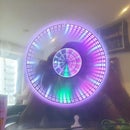
Step 6: Final Result


Features:
- Works like a clock - the colours of the hands are user-programmable over bluetooth
- Has an IR sensor to sense if someone is coming near the mirror. Switches off the LEDs, so that this can be used as a normal mirror :-)
- Shows a rainbow effect every 15 minutes (time is user adjustable)
- Has a touch button to toggle between clock and rainbow effects
- Switches to night mode between midnight and 7:00 AM - can be changed in the code.
- Can be programmed over bluetooth - so you do not need to take it off the wall if you need to update the code
The clock can be programmed over bluetooth using the following commands:
- MULTI - Toggles the multi-coloured rainbow effects
- STAT - Provides the clock status to the serial port
- SETRAIN Sets the interval for the rainbow effects - e.g every 5 minutes: SETRAIN 5
- HOUR [R] [G] [B] Sets the colour of the hour hand - e.g. HOUR 255 0 0 sets the hour hand to Red
- MIN
[R] [G] [B]
Sets the colour of the minute LEDs - e.g. MIN 0 255 0 sets the minute LEDs to Green - SEC[R] [G] [B] Sets the colour of the second LED - e.g. SEC 255 255 255 sets the second LED to White
- BG [R] [G] [B] Sets the colour of the background LEDs - e.g. SEC 30 30 30 sets the background LEDs to Grey
- LIGHT [NIGHT] [DAY] Sets the brightness of the LEDs during night time and day time - e.g LIGHT 0 150 switches off LEDs at night and sets brightness to 150 during day. The code currently considers time between midnight and 7:00 AM as night. This can be changed easily in the code
- TIMESet the time
In addition, the clock can also be used as a physical notifier for missed calls on smartphones (http://dushyant.ahuja.ws/2013/11/physical-android-... Unfortunately, the android code in the link has stopped working. Can anyone help me in creating a tasker plugin that sends a serial text (placed in a variable) via bluetooth to the arduino.
Step 7: Problems Faced
Even though this build is relatively simple, I faced a few problems while building:
- The dimensions of the circles are very important. As I did not have access to a laser cutter, the circles have been cut by hand (not by me) and I faced problems while fixing the LED strip and the glass. I had given the dimensions to the carpenter in mm - but carpenter was used to inches and hence there was a slight rounding off in the dimensions. The center circle where the LED strip has to be stuck HAS to have a circumference of exactly 1000mm for the LED strip to fit correctly. The carpenter had made a larger circle and I had to pad the circumference with double sided tape. The outer circles where the mirror and glass had to be installed had the opposite problem - the glass simply did not fit. So I had to manually file the plywood to make the glass fit. My suggestion here would be to get the glass cut first and take it with you when you get the plywood cut. Would make things so much simpler. Luckily the design allows for small problems in the dimensions and you cannot see the faults in the final build
- I had assumed that a 7805 with a heat-sink would be sufficient to power the clock, as I had made a similar circuit before and it worked without any problem. I had not counted on the fact that these LEDs are behind a one-way mirror and consequently have to be much brighter. The first trial run had the processor hanging whenever the rainbow effects came on, the bluetooth module getting disconnected, etc. Thanks to friends on the arduino and fastled forums - I was able to sort this out. Bought an LM2596 module to power the LED strip separately. This module can pump out 3A with a heatsink. While this is still not enough for the 3.6A the strip can pull at full white, the software never turns on all the LEDs to white - so this is not a problem. Furthermore, I have added a night mode to the clock, so that the power supplies and LEDs can cool down at night - and hopefully prolong their life.
- The touch button is still giving some problems - but I think that is more to do with the problems in earthing in my house rather than anything else. Will try it at a friend's house to see if I still get the same problem.
- The proximity sensor does not work through glass. I had thought of installing the sensor behind the one-way mirror, but the glass blocks IR and hence the sensor does not work. I had to install it below the clock - its not big enough to be a distraction or look bad, but is not perfect either.
- Planning - I would suggest you plan all the features before you start building. My wife came up with the idea of converting this to a smart mirror (also) and I had to cut out the LCD enclosure with the limited tools I had at home (a drill and a file) - which was a problem. Had we planned for this enclosure earlier, we could have got a better finish.
- Costs - I had budget around 2,000 INR for this build, but we changed the design mid-way and added more features - so the final cost went over 5,000 INR. But I still love the final result :-)
Step 8: Future Plans
- Add a TFT LCD behind the one-way mirror to make it a smart mirror. The TFT LCD would show time, weather, a joke (?). The intent is to switch on the TFT when the LEDs are off so that it shows up through the on-way mirror. Similar to this: http://www.homecrux.com/2013/10/12/9583/smart-mirr...
- Add a microphone so that beat detection can be incorporated and effects setup to match the music
- Use it as a physical notifier to provide notifications for missed calls, texts, etc from my smartphone. The TFT LCD can be used to display the name, text, etc.
Suggestions welcome
Step 9: References and Links
Project github: https://github.com/dushyantahuja/Smart-Infinity-Mirror
Inspirations:
- Charlieplexed LED Clock: https://www.instructables.com/id/Arduino-controlled-RGB-LED-Infinity-Mirror/
- Arduino-controlled RGB LED Infinity Mirror: https://www.instructables.com/id/Arduino-controlled-RGB-LED-Infinity-Mirror/
- Simple IR proximity sensor with Arduino: https://www.instructables.com/id/Arduino-controlled-RGB-LED-Infinity-Mirror/
Arduino Libraries:
- AdaFruit RTCLib: https://github.com/adafruit/RTClib
- FastLED Arduino Library v2.1: http://fastled.io/https://github.com/FastLED/FastLED/tree/FastLED2.1
- SerialCommand Arduino Library: https://github.com/scogswell/ArduinoSerialCommand
- TimerOne Arduino Library: https://code.google.com/p/arduino-timerone/

Runner Up in the
Epilog Challenge VI

Participated in the
Home Technology Contest


