

Introduction: Input & Output (Digital & Analog)


In this instructable, we will cover input and outputs, for both digital and analog signals.
Step 1: Digital
The digital input and output pins on the Arduino board are what allow you to connect the micro-controller to your sensors and controllers. By understanding how they work, it will allow you to do many useful things, such as reading switch inputs, and controlling relay outputs.
Step 2: Digital Signals
Unlike analog signals, which we will cover later in this tutorial, digital signals have only two distinct values: HIGH (1), and LOW (0). Digital signals will be used in situations where the input or output will have one of these values. For example, when using a digital signal to turn an LED on or off.
Step 3: Digital Functions
The Arduino functions associated with digital signals that we will be using are:
- pinMode()
- digitalWrite()
- digitalRead()
pinMode(pin, value)
This function is defined by two parameters, pin, and mode.
pin: This is the number of the pin, whose mode you wish to set.
mode: This can be set to INPUT, OUTPUT, or INPUT_PULLUP. When mode is set to INPUT_PULLUP, a 20 kohm pullup resistor is internally connected to the pin to force the input HIGH if there is nothing connected to the pin.
digitalWrite(pin, value)
This function writes a digital value to a pin.
pin: This is the number of the pin the digital value will be written to.
value: This is the digital value which the pin is set to. This value must be either HIGH or LOW.
digitalRead(pin)
This function reads a digital value from a pin and returns one of two values: HIGH, or LOW.
pin: This is the number of the pin whose value you want to read.
Step 4: Digital Input & Output Examples (Blinking LED)

Blinking LED
Required Hardware:
- 1 x LED
- 1 x 220 ohm resistor
- 1 x breadboard
- 2 x wires
The diagram above shows how to connect the LED, and resistor, to the Arduino. As shown, the LED connects to the digital pin 8 of the Arduino, through the resistor.
Programming: The following code configures pin 8 to be an OUTPUT, then sets the digital I/O pin to HIGH for 1000ms, and then to LOW for another 1000ms
const int led = 8; //use digital I/O pin 8
void setup(){
pinMode(led,OUTPUT); //set pin 8 to be an output
}
void loop(){
delay(1000); //delay 1000 milliseconds
digitalWrite(led,HIGH); //set pin 8 HIGH, turning the LED on
delay(1000); //delay 1000 milliseconds
digitalWrite(led, LOW); //set pin 8 LOW, turning the LED off
}
Once the code is uploaded to the Arduino, the LED should blink on and off.
Step 5:
Blinking LED Using a Button
In the previous example, we only used a digital output. In this example, however, we will also use a digital input in the form of a button. By pressing a push-button connected to a digital input we can turn the LED on or off.
Required Hardware:
- 1 x LED
- 2 x 220 ohm resistor
- 1 x push-button switch
- 1 x Arduino
- 1x Breadboard
- 6 x Wires
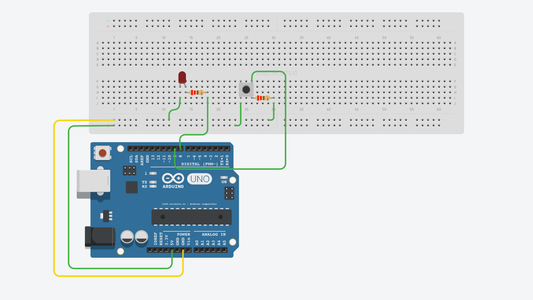
An LED is connected to pin 8, which is configured as an OUTPUT. A push-button is connected to pin 9, which is configured as an INPUT. When someone presses the push-button switch, pin 9 is set to HIGH, and the program will then set the output of pin 8 to HIGH and turn on the LED. Releasing the push-button rests pin 9 to LOW and, as a result, the program sets pin 8 to LOW, turning the LED off.
Programming:
const int led = 8; //name pin 8 as LED
const int button = 9; //name pin 9 as button
void setup(){
pinMode(led,OUTPUT); //set pin 8 as OUTPUT
pinMode(button,INPUT) ; //set pin 9 as INPUT
}
void loop(){
int reads = digitalRead(button); //read the digital value on pin 9
digitalWrite(led,reads); //set the digital output value of pin 8 to that value
}
Step 6: Analog
Even though the Arduino microcontrollers are purely digital devices which work with either a HIGH or LOW value, they are commonly used with analog systems. This is achieved with the use of an Analog to Digital Converter (ADC), and works by sampling the analog input voltage, and then converting it to their respective digital values.
The Arduino can also produce an analog voltage with the use of its built in Pulse Width Modulation (PWM) module.
Step 7: Analog Functions
- analogRead()
- analogWrite()
- analogReference()
analogRead(pin)
This function reads the value from the specified analog pin. The Arduino board contains a 6 channel (8 on the Arduino Nano, which we will be using), 10-bit analog to digital converter. This means that it will map input voltages between 0 and 5 volts into integer values between 0 and 1023. This yields a resolution of 0.049V (4.9mV) per unit. The input range and resolution can be changed using the analogReference() function.
pin: The number of the analog input pin to read from (0 to 7 on the Nano).
Note: If the analog input pin is not connected to anything, the value returned by analogRead() will fluctuate based on a number of factors (e.g. the values of the other analog inputs, how close your hand is to the board, etc)
Example:
int analogPin = 3; // potentiometer wiper (middle terminal) connected to analog pin 3
// outside leads to ground and +5V
int val = 0; // variable to store the value read
void setup(){
Serial.begin(9600); // setup serial
}
void loop(){
val = analogRead(analogPin); // read the input pin
Serial.println(val); // debug value
}
analogWrite(pin, value)
This function writes an analog value (PWM wave) to a pin. This can be used to light an LED at varying brightness levels or drive a motor at various speeds. After a call to analogWrite(), the pin will generate a steady square wave of the specified duty cycle until the next call to analogWrite() (or a call to digitalRead() or digitalWrite() on the same pin). The frequency of the PWM signal is approximately 490Hz.
On most Arduino boards, this function works on pins 3, 5, 6, 9, 10, and 11.
You do not need to call pinMode() to set the pin as an output before calling analogWrite().
pin: This is the number of the pin, to which you wish to write the value to.
value: This is the duty cycle: between 0 (always off) and 255 (always on).
Example
int ledPin = 9; // LED connected to digital pin 9int
analogPin = 3; // potentiometer connected to analog pin 3
int val = 0; // variable to store the read value
void setup(){
pinMode(ledPin, OUTPUT); // sets the pin as output
}
void loop(){
val = analogRead(analogPin); // read the input pin
analogWrite(ledPin, val / 4); // analogRead values go from 0 to 1023, analogWrite values from 0 to 255
}
analogReference(type)
This function configures the reference voltage used for analog input (i.e. the value used as the top of the input range).
Type: This can be set to one of three different configurations:
- DEFAULT - The default analog reference of 5V on 5V Arduino boards, or 3.3V on 3.3V Arduino boards.
- INTERNAL - This is a built-in reference, equals 1.1V.
- EXTERNAL - The voltage applied to the AREF pin (0V to 5V) is used as the reference.
Note: After changing the analog reference, the first few readings from analogRead() may not be accurate. Don’t use anything less than 0V or more than 5V for external reference voltage on the AREF pin! If you are using an external reference on the AREF pin, you must set the analog reference to EXTERNAL before calling analogRead().


