

Introduction: Insect Bot Mini


Well, what is the Insect Bot. Actually it's not really an insect because it only has four legs, insects does have six of them, right? However, the robot got the name because of his shape with the thin wire legs and the IR sensor rosed up.
That robot already has a long history. first I built one with standard servos and an Arduino UNO but soon I wanted it smaller and even more easy to build. After a couple of attempts with different designs this one is the final one.
Here you can see the big one: letsmakerobots.com/node/26194
The following is the step by step description, how to assemble the robot and if you are already a bit skilled in such things then it will not take you more than one hour of your time.
This first video shows how the robot could walk after switching it on for the first time and without adjusting the legs :-)Step 1: Servos Building the Body


Stick both servos together by using double sided foam tape. Front servo shaft in top and rear servo shaft on the backside.
Make sure you align them properly that they build a nice body for the robot.
Step 2: Servos Wrapped


Wrap a big cable tie (4x200mm) around the two servos to secure them. Pull the cable tie very tight to strap the servos together. You may use pliers to give it the final pull.
Step 3: Bending the Legs


Bend the wire in a V shape like shown in the picture. The tips of both wire ends should be 100mm apart. Don't worry about precision yet, you will have to bend them later in the right shape anyway.
Bend about 10mm of the round end to 90° The bending quality depends on the wire you are using. I am using stainless steel 304 with 1mm diameter. That sort of wire you can still bend with your fingers and it will stay in the shape you gave it. However, the 90° bend needs to be quite sharp to fit, so please bend it as close to the pliers edge as possible.
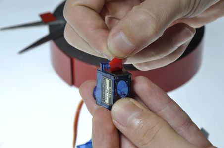
Step 4: Attaching Legs to the Servo Horn


Put the two ends of the wire leg through the second hole from the center and then bend the two legs apart as seen in the picture. Hold the wire leg and the servo horn with pliers and bend the wire close to the servo horn down.
You may use the servo horn shown on the picture or any other one which comes with those micro servos.
Step 5: Attaching the Legs to the Servos


Attach the servo horns with the wire legs to the servo by fixing them with the small screw. For that step I assume that you are familiar with Arduino and how to center a servo. Please center your servos before that step. If your servos are not centered then you may fix that later after switching the robot on for the first time.
Bend the legs in a shape that the robot is standing nicely and stable.
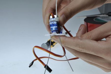
Step 6: Sensor Holder


Use scissors to cut the sensor holder out of a plastic sheet, cardboard or aluminum, well you even could use a Dremel tool and cut it out of an old CD/DVD. Make sure the upper part is minimum 45mm wide to attach the infrared sensor.
The base need to be 10mm wide to attach the holder on the servo.
Optional: Bend the end about 5mm to double the material thickness, if you are using thin plastic in order to have more grip for the screw. Punch/drill a tiny hole in the bottom. These holes should not be bigger than the diameter of the screw to guarantee the screw is holding. Attach the sensor holder with a screw from the servo accessory at the top of the front servo.
Step 7: Attaching the Sensor to the Sensor Holder


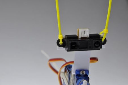
Make two holes for the infrared sensor by placing the sensor on the holder and mark the holes. Then make the holes with with 2mm diameter using scissors or another suitable tool. Fix the sensor with the white connector facing up on the holder by using two small cable ties. You may cut the cable ties but they are good to use them as antennas or feelers as seen by insects.
The sensor also could be attached using some suitable bolts and nuts but then you will not have those nice antennas on that insect head :-)
Step 8: Solder the Beetle on the Beetle Shield


Now it's time to solder the Beetle controller onto the Beetle shield. First you have to put the beetle on the pins by paying attention to the right direction. The USB socked needs to face to the left side of the shield, the side where these two mounting holes are located.
You need to solder the pics for “D9”, “D10”, “D11”, “A0”, “A1” and “A2” as well the two power pins labeled with “+” and “-”.
Note: The Beetle is DFRobots tiny Arduino compatible MCU board with 3x digital I/O and 3x analog I/O as well solder pads for RX/TX and four I/O's on the backside of the board. The Beetle Shield is for now only available in the Insect Bot mini kit
Optional: You may use any other MCU which fits but so far the Beetle or the previous version the Cheapduino is small enough.
Step 9: Assembling the Battery, Board Backpack


Use two sticky pads on each side of the battery. Then stick the battery on the bottom of the PCB and make sure it's aligned to the front. Remove the protective layer of the bottom side of the battery and stick the whole battery-board-assembly on the rear servo.
Make sure the battery wire is facing to the right to connect it with the power connector on the Beetle shield.
Warning! Make sure that you not puncture the LiPo battery with the leads on the bottom side of the Beetle Shield. Use double sided foam tape with minimum 3mm thickness to prevent that from happening.
Step 10: Wiring Up


If you are using the provided code then you need to connect the servos and the sensor as followed.
Connect the front servo cable with D9 on the PCB and the rear servo with D10.
Make sure that the yellow wire is facing inwards to the Beetle board in the middle of the PCB.
Connect the white plug of the sensor cable with the socket on the infrared sensor and the black plug with connector A1 on the PCB. This cable needs to be connected with the blue wire facing inwards to the Beetle on the PCB.
To make sure that you've got the right cable please check the Wiki http://www.dfrobot.com/wiki/index.php/Insect_bot_mini
The last task is to connect the battery with the battery pins on the PCB. Make sure the red wire is connected with VCC and the black wire is connected with GND. After pressing the switch to power up the robot, the LED on the PCB should light up.
Step 11: Programming the Insect Bot Mini


The connected Beetle will show up as a Leonardo. Please choose this and select the proper COM port.
Open the previous downloaded file insect_bot_smooth_en.ino from below that instrucable and upload it to the Beetle.
Once it's done without errors the Insect Bot mini is ready to take his first steps.
The complete Insect Bot mini kit is available at DFRobotand comes with all the parts plus rechargeable LiPo battery with USB charger.
Time lapse video of the assembling:
Attachments

Step 12: Workshops and Other Stuff


That little robot is quite a star in our local Shanghai Hackerspace Xinchejian. We did many workshops for kids building them. These kids had a lot of fun and each one of the robots was looking different after finishing it. The kids used any materials left from the build to decorate them, glued feet on the wire legs or did cut the sensor holder in different shapes.
Here some pictures about these workshops and creations:
Cup robot:http://xinchejian.com/2011/04/25/insect-bug-in-a-cup/
Workshop in Xinchejian:http://xinchejian.com/2011/05/09/insect-bot-workshop-2/
Workshop during Maker Carnival in Shanghai:http://letsmakerobots.com/node/38849
Helpful notes from userhabsinn: https://hackpad.com/INSECT-BOT-WORKSHOP-I1ZTtSBlnaH
Thanks for reading till the end :-)

Participated in the
Workshop Contest


