

Introduction: Intelligent-Light


Hello Makers,
Want to know why your monthly electricity bills are "so high"? This is because when a person inside the room leaves the room hastily, he or she unknowingly leave the lights and fans switched on.
There are many solutions to solve this problem, but the solutions are not adaptive and cost-effective.
So, what’s next? The only way to solve this is to use an Intelligent Light System. In this system when a person enters the room the tube lights are switched on automatically and go off automatically when there is nobody inside the room. This implies that the whole system is now at the tip of your motion.
Step 1: Components Needed


All that you need is:
Hardware Required
- NodeMCU
- 5V Relay Board
- Bread Board
- 3W LED Bulb
- IR sensor (x2)
- Enclosure
- 2-pin Plug (x1)
- Socket Bulb Holder (x1)
- Micro USB cable
- Electrical Wires
Software Required
- Arduino IDE (with ESP8266 Library installed)
Step 2: Enclosure Fabrication


- Draw a square of 3cm x 3 cm ( this varies according to the size of the bulb holder ).
- Within the circle make a circle with a radius of 1.5cm / the circle diameter should be 3cm.
- Using Dremel tool cut the circle portion to make some space to fix the bulb holder.
- Next, you need to make few holes according to your IR sensor placement. I've made holes in front of the enclosure.
- Now using driller you can drill the holes. If you don't have driller, you can use a solder gun to make some holes.
- You can now fix the bulb holder into space created. You can use glue to fix the holder permanently.
OK, let'sm move to circuit part.
Step 3: 220v Supply Connection


- Connect the Livewire from 2-pin plug to one of the holder terminals.
- Connect the Ground wire of the supply to COM pin of the Relay.
- Connect a wire from NC (Normally Closed) of the relay to another terminal of the bulb holder.
If any confusion refer the connections as shown in the image below.
Step 4: Realy Connection


Relay connections are as follow:
- The positive supply pin (+V) is connected to Vin pin of NodeMCU.
- The negative pin (GND) is connected to GND pin of NodeMCU.
- The Input pin of the relay is connected to Digital Pin D0 pin of NodeMCU.
You can also refer my previous Instructable how toInterface Relay Module with NodeMCU
Step 5: IR Sensor Connections


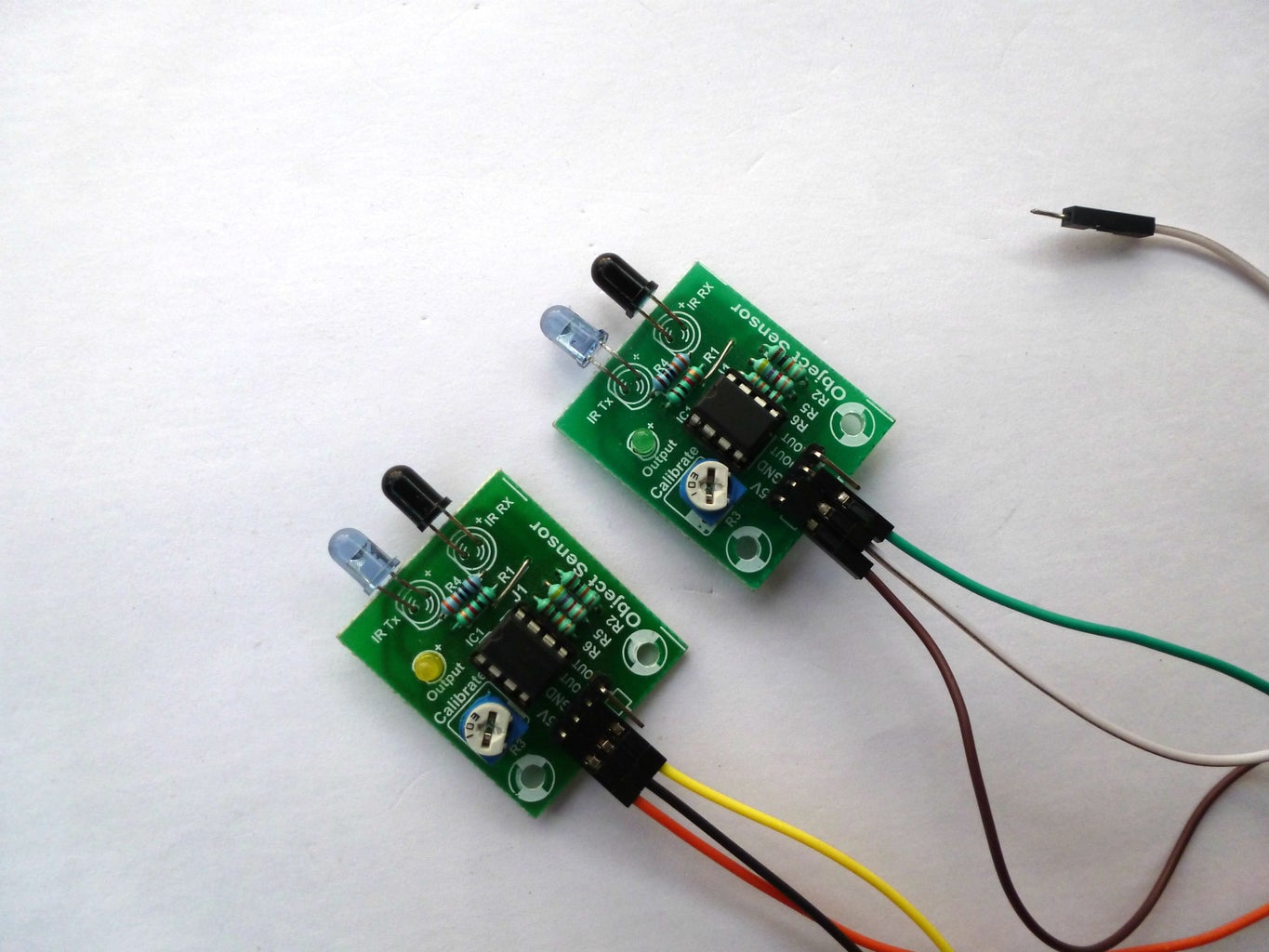
IR sensor1 Connection:
- The Vcc pin of the IR module is connected to +3v of the NodeMCU.
- The Output pin of the IR module is connected to Digital pin D1 of the NodeMCU.
- The GND pin of the IR module is connected to the Ground pin (GND) of the NodeMCU.
IR sensor2 Connection:
- The Vcc pin of the IR module is connected to +3v of the NodeMCU.
- The Output pin of the IR module is connected to Digital pin D2 of the NodeMCU.
- The GND pin of the IR module is connected to the Ground pin (GND) of the NodeMCU.
You can also refer my previous Instructables on how to Interface IR Module with NodeMCU
Step 6: Assembly


Finally, assemble all the components and wires into the Enclosure.
Well Done. We have completed with the device, let's test it.
Step 7: OUTPUT

Now, you can develop this instructable with various sensors and implement in many other applications.
That's all makers!
I hope you found this instructable most innovative. You can contact me by leaving a comment. If you like this instructable probably you might like my next ones.

Runner Up in the
Automation Contest 2017

Participated in the
Makerspace Contest 2017

Participated in the
Home Improvement Contest 2017


