

Introduction: Interface Lcd With Arduino Beginner Guide


Part to be Required
1.JHD162A LCD
2.Arduino board
3. potentiometer
4.jumper wires
What is LCD?
LCD (liquid crystal display) is the technology used for displays in notebook and other smaller computers. Like light-emitting diode (LED) and gas-plasma technologies, LCDs allow displays to be much thinner than cathode ray tube (CRT) technology. LCDs consume much less power than LED and gas-display displays because they work on the principle of blocking light rather than emitting it.
An LCD is made with either a passive matrix or an active matrix display display grid. The active matrix LCD is also known as a thin film transistor (TFT) display. The passive matrix LCD has a grid of conductors with pixels located at each intersection in the grid. A current is sent across two conductors on the grid to control the light for any pixel. An active matrix has atransistor located at each pixel intersection, requiring less current to control the luminance of a pixel. For this reason, the current in an active matrix display can be switched on and off more frequently, improving the screen refresh time (your mouse will appear to move more smoothly across the screen, for example).
The name and functions of each pin of the JHD162A LCD module is given below.
Pin1(Vss):Ground pin of the LCD module.
Pin2(Vcc):+5V supply is given to this pin
Pin3(VEE):Contrast adjustment pin. This is done by connecting the ends of a 10K potentimeter to +5V and ground and then connecting the slider pin to the VEE pin. The voltage at the VEE pin defines the contrast. The normal setting is between 0.4 and 0.9V.
Pin4(RS):Register select pin.The JHD162A has two registers namely command register and data register. Logic HIGH at RS pin selects data register and logic LOW at RS pin will select command register. If we make the RS pin HIGH and put a data on the data lines (DB0 to DB7) it will be recognized as a data. If we make the RS pin LOW and put a data on the data lines, then it will be taken as a command.
Pin5(R/W): Read/Write modes. This pin is used for selecting between read and write modes. Logic HIGH at this pin activates read mode and logic LOW at this pin activates write mode.
Pin6(E): This pin is meant for enabling the LCD module. A HIGH to LOW signal at this pin will enable the module.
Pin7(DB0) to Pin14(DB7): These are data pins. The commands and data are put on these pins.
Pin15(LED+): Anode of the back light LED. When operated on 5V, a 560 ohm resistor should be connected in series to this pin. In arduino based projects the back light LED can be powered from the 3.3V source on the arduino board.
Pin16(LED-): Cathode of the back light LED.
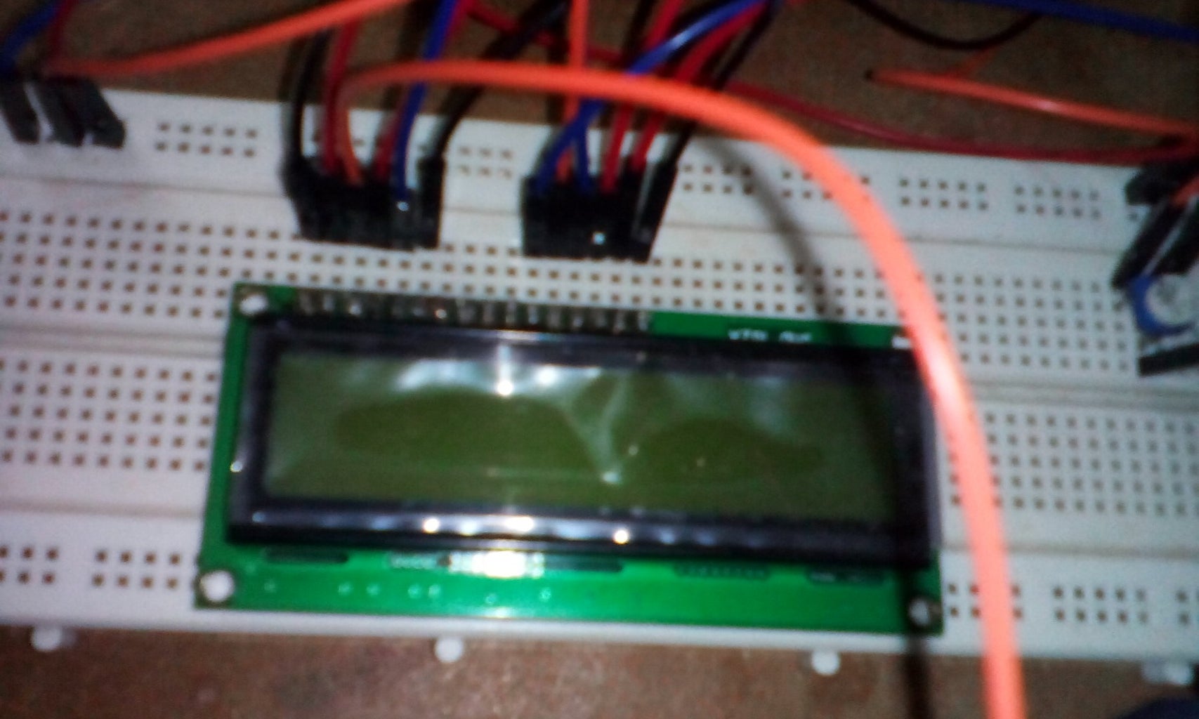
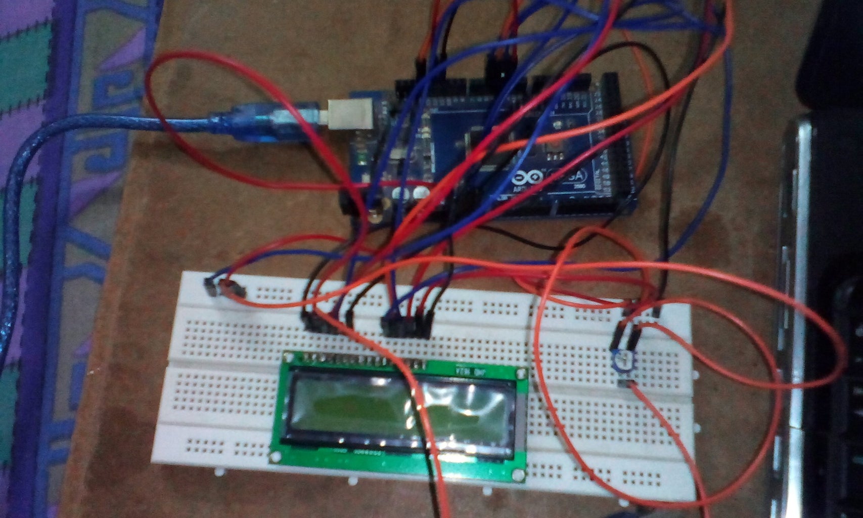
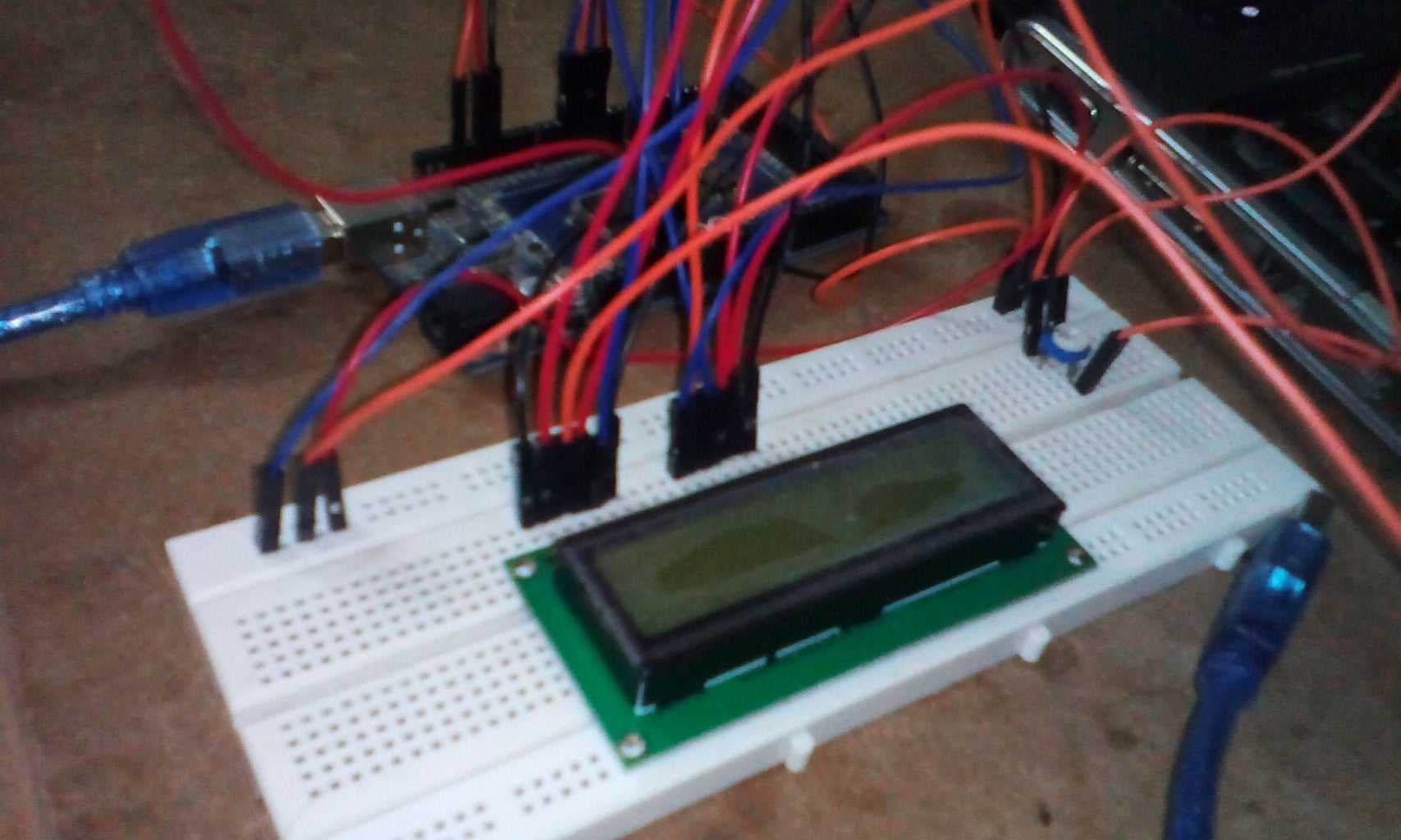
Step 1: Make a Breadboard Circuit and Set Contrast With Potentiometer

program for display text on Lcd screen
#include
LiquidCrystal lcd(12, 11, 5, 4, 3, 2); // sets the interfacing pins
void setup() { lcd.begin(16, 2); // initializes the 16x2 LCD }
void loop() { lcd.setCursor(0,0); //sets the cursor at row 0 column 0 lcd.print("16x2 LCD MODULE"); // prints 16x2 LCD MODULE lcd.setCursor(2,1); //sets the cursor at row 1 column 2 lcd.print("HELLO WORLD"); // prints HELLO WORLD
}
Arduino IDE provides Liquid Crystal Library Which includes Standard Program . See the Below Demo video which includes All example of Liquide crystal display ..


