

Introduction: Interface Multiple LCD to Arduino Uno Using Common Data Line


Today, in this instructable i am going to show you how to interface multiple 16x2 LCD module with an arduino uno board using common data line. The most interesting thing about this project is, it uses common data line and display different data in each LCD.
Step 1: Step 1: Electronic Parts

- Arduino Uno: 1 piece
-16x2 LCD: 4 piece
-10k Ohm Potentiometer: 4 piece
-470 Ohm Resistor: 4 piece
-Bread board
-Jumper wires
Step 2: Step 2: the Code
At first you have to define the pin of LCD with common data line
LiquidCrystal lcdA(13,12,7,6,5,4);
LiquidCrystal lcdB(11,10,7,6,5,4);
LiquidCrystal lcdC(9,8,7,6,5,4);
LiquidCrystal lcdD(3,2,7,6,5,4);
From above definition code you can see that, all the data line of LCD (LCD1 LCD2 LCD3 and LCD4) are connected to same arduino board digital pin (D7, D6, D5 and D4) while RS and EN pin is connected to individual digital pin.
Here the complete code for our project:
#include
LiquidCrystal lcdA(13,12,7,6,5,4); //pin definition for LCD 1
LiquidCrystal lcdB(11,10,7,6,5,4); //pin definition for LCD 2
LiquidCrystal lcdC(9,8,7,6,5,4); //pin definition for LCD 3
LiquidCrystal lcdD(3,2,7,6,5,4); //pin definition for LCD 4
void setup()
{
lcdA.begin(16,2); //Initializes of LCD 1
lcdB.begin(16,2); //Initializes of LCD 2
lcdC.begin(16,2); //Initializes of LCD 3
lcdD.begin(16,2); //Initializes of LCD 4 }
void loop()
{
lcdA.setCursor(0,0);
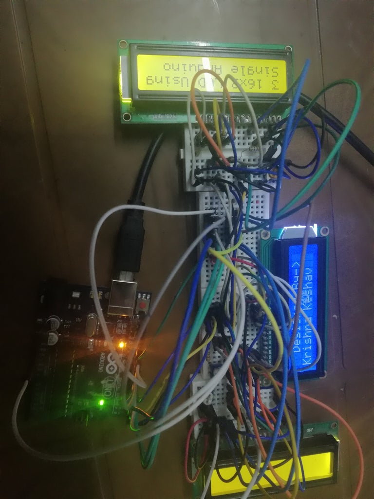
lcdA.print("3 16x2 LCD Using");
delay(100);
lcdB.setCursor(0,0);
lcdB.print(" Designed By-> ");
delay(100);
lcdC.setCursor(0,0);
lcdC.print("Visit Website");
delay(100);
lcdD.setCursor(0,0);
lcdD.print("BestEngineering");
delay(100);
lcdA.setCursor(0,1);
lcdA.print("Single Arduino");
delay(100);
lcdB.setCursor(0,1);
lcdB.print("Krishna Keshav");
delay(100);
lcdC.setCursor(0,1);
lcdC.print("and Subscribe");
delay(100);
lcdD.setCursor(0,1);
lcdD.print("Projects");
delay(100);
}
Step 3: Step 3: Build the Circuit


The circuit posted here is designed using proteus 8 Professional.
In proteus pin no. 15 and 16 of LCD is hidden thus, i made connection for pin 15 and 16 (anode and cathode of LCD) which pin is used for back-light for LCD.
Step 4: Step 4: All Done

Hope this project will help you.
If you have any queries or want more awesome project please visit bestengineeringprojects.com


