

Introduction: Network Time Syncronized Clock for Arduino


Here is an example how to build Arduino clock which is syncronized with the time of given HTTP server in the net. My plan was to build simplest possible internet time syncronized clock. I decided to synchronize my Arduino clock with my Wlan router's time, the router itself is synchronized to the network time (NTP) time. Instead of NTP protocol, I am using HTTP protocol date field (in HTTP header) of my Wlan router to syncronize this clock.
Component list
- Arduino nano (any Arduino will do)
- ESP8266 wlan chip (note that this chip requires 3.3V power and shouldn't be used with 5V)
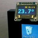
- 0.96" 128x64 pixel OLED display
- level converter or voltage divider (with resistors) for converting Arduino 5v to 3.3V suitable for ESP8266
- 3.3V power supply (Arduinos 3.3V power output isn't quite enough for Wlan chip)
Step 1: Connect Arduino and OLED Display
OLED  Arduino
-------------
SDA   D9
SCL   D10
RST   D13
D/C   D11
VCC   5V
GND   GND
Step 2: Connect ESP8266 Wlan Chip to Arduino
Note that this chip is using 3.3V and connecting it directly to 5V will most probably break it. Voltage level conversion for data lines is necessary, simple resistor voltage divider is sufficient for converting Arduino's 5V TX to ESP8266 RX, you probably don't need any level converter for ESP8266 TX (3.3V) to Arduino's RX, as 3.3V is enough to drive Arduino's input.
Remember that this chip requires lots of current (200-300mA?) , so you may need a separate power supply for 3.3 Volts.
ESP8266 Reset pin needs to be connected to 3.3V or you may use software to control reset line (remember max 3.3V 'high' and use level converter or voltage divider here too).
ESP8266 Arduino
---------------
VCC     3.3V      Don't use 5V for ESP8266
GND     GND
TX      D3        Software serial port receiver (configurable),
                  no level converter needed for input
RX      D4        Software serial port transmitter (configurable),
                  USE LEVEL CONVERTER (5v->3.3v) for example as shown below
RESET   3.3V      Connect directly to 3.3V or use Arduino output pin with
                  level converter to reset the WLAN when needed
Simple voltage divider (Arduino 5V D4 -> ESP8266 RX) for level conversion
Arduino D4 (0 to 5V data out)
         |
        1k ohm resistor
         |
         +--------  ESP8266 RX (0 to 3.3V data in)
         |
        2k ohm resistor
         |
         |
        GND
Step 3: Modify and Upload Software to Arduino
- Set the SSID of the router (SSID)
- Set WLAN password (PASS)
- Set IP address of the server (WLAN router) (DST_IP).
HTTP 'GET' request will be sent to this address. HTTP header of the response contains 'Date' attribute with current time (GMT). For example: Date: Sat, 28 Mar 2015 13:53:38 GMT
You should use your Wlan router at home as a 'time server' or any other server in the internet if you can't get correct time from your local router. - Set the local time zone and daylight savings time as the received date field is always in GMT (UTC) time
- Translate local weekdays to your language and set the date format as you wish (Day, dd.mm.year)
Note that ESP8266 is controlled by serial line and serial line buffer size of Arduino is only 64 bytes and it will overflow very easily as there is no serial line flow control. Because of that, additional reset line to WLAN chip may be necessary as described in the original HTTP client code (link for reference).
The software is using Arduino SoftwareSerial library to and OLED code originally from How to use OLED.
Here is my code on GitHub


