

Introduction: Introducing the Microcontroller + Arduino


So far you have turned on an LED by connecting a power source (battery) to your circuit. What if you wanted to control the LED another way? For example, have the LED blink when a button is pressed? Or, what if you want to sense when someone is giving you a big hug or bending their elbow? You need something that can be told to read data, manipulate it and then do something in response. A microcontroller can do all these things! In this lesson, you will be introduced to what a microcontroller is and how to work with one.
You will learn:
+ the parts of a microcontroller
+ the meaning of digital, analog, input, output and PWM
+ how to download and install the Arduino IDE
Step 1: What Is a Microcontroller?
A microcontroller board is a mini computer and can be thought of as the brains of your circuit.
The board has input and output pins, which allow you to hook up various devices such as a switch (input) and an LED (output). There is a microcontroller chip on the board that you upload a program to tell it to perform a specific task. This program tells the microcontroller what to do with that switch and LED or any other inputs and outputs that are connected to the board.
For example, the program can tell the board to turn the LED on for 4 seconds, then off for 1 second each time you press the switch. Being able to program different behaviors means you can get endless possibilities with one circuit.
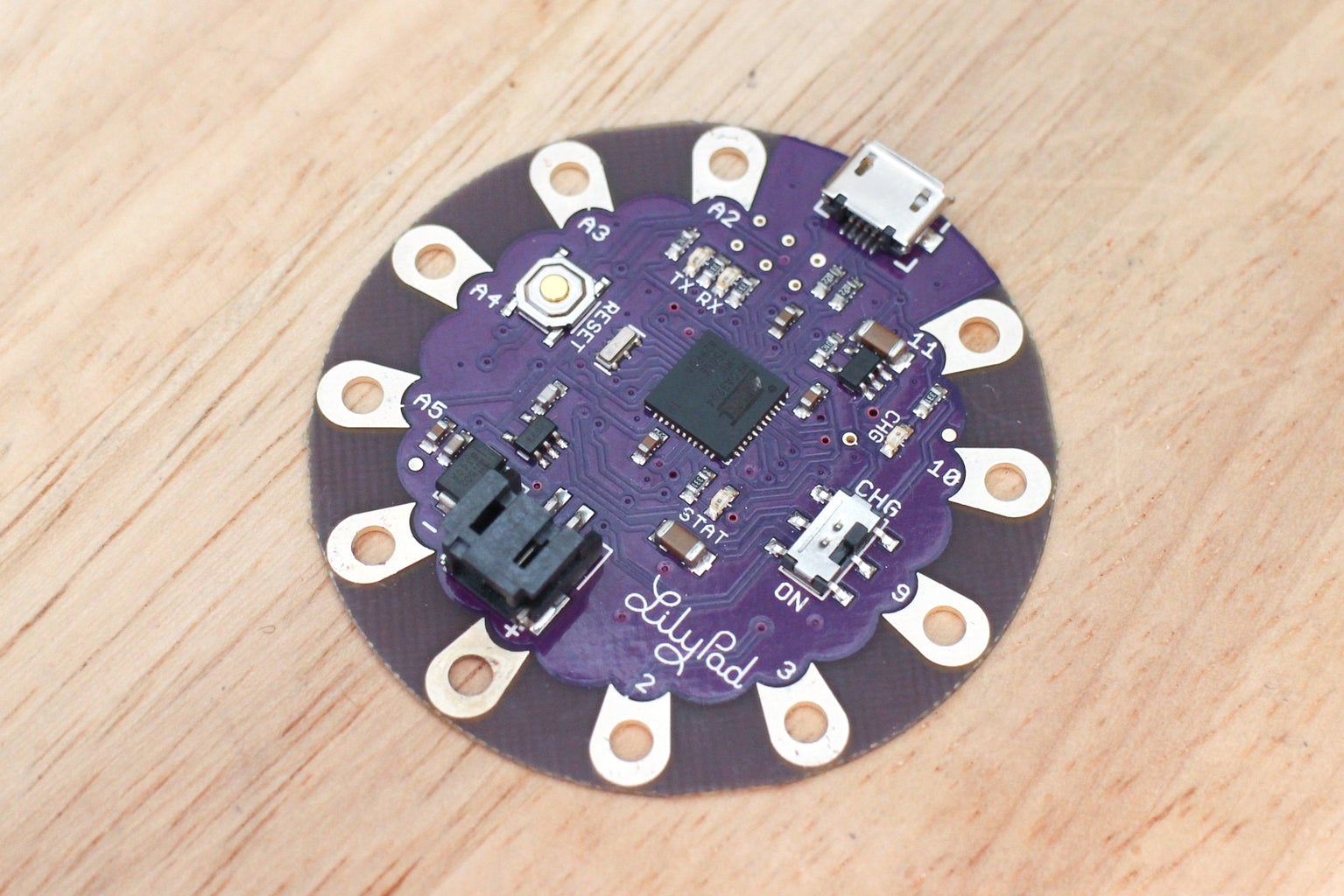
In this class, you will be working with the LilyPad USB microcontroller and learning how to upload programs to it using the open-source Arduino software. In this lesson, you will be introduced to important concepts. Don't worry if you do not absorb them all now, you will putting some of these concepts into practice in later lessons.
Step 2: Pins of a Microcontroller
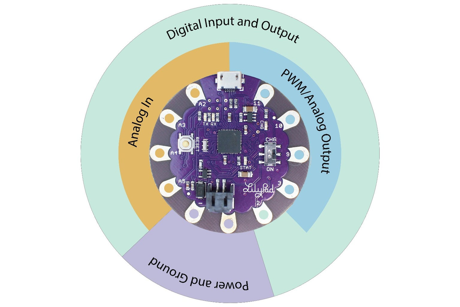
The pins on a microcontroller are what you connect your components and sensors to. On the LilyPad USB, these pins are large metal pads with holes through them making them easy to sew and clip to.
Not all pins on a microcontroller are capable of the same functions. To know which pin to use, you will need to know what kind of component you are working with and what kind of behavior you want. The terms below are ways of categorizing components and the electrical signal they and the microcontroller produce. Before you build a circuit and program your board, let's go over these terms and concepts. It will be helpful to bookmark this to reference later on.
+ Digital
+ Analog
+ Input
+ Output
+ PWM (Pulse Width Modulation)
Step 3: Digital Input and Output

A digital signal is one that goes from a maximum voltage to 0 volts. Each microcontroller outputs a maximum voltage, your LilyPad USB outputs 3.3v. When the signal is running at 3.3 volts this translates to 1. When it is at 0 volts, this translates to 0. A digital signal has just these two states.
There are words that generally mean the same thing when talking about digital logic within the Arduino software. I will use them interchangeably throughout the class and you will use them later when working with the Arduino code.
HIGH/1/On
When an electrical signal on your board is pulled HIGH, this is read as 1 and outputs 3.3 volts. If an LED is on the pin that is pulled HIGH, it turns on since it gets those 3.3 volts.
LOW/0/Off
When an electrical signal is pulled LOW, this is read as 0 and outputs 0 volts. If an LED is on the pin that is pulled LOW, it turns off since it gets 0 volts.
Digital Input - When you want to sense something in the world, sometimes the only thing you need to know is whether something is true or false. Did the cat hit the toy? Did I clap my hands? Did the door open? These are yes or no questions, binary in logic, resulting in a 0/1. Devices that have two states, like a switch, are digital and are read through a pin that uses digital logic. The microcontroller collects these state changes through digital input pins which can be used to trigger events.
Digital Output - Similar to how the digital input can sense an action with two states, a digital output pin can control an action with two states. For example, it can turn an LED to HIGH (1) and LOW (0), turning it on and off.
Step 4: Analog Input and Output

An analog signal is one that varies. It does not just have two states, such as on and off. It has a variable one that reads 0V and 3.3V and all the voltage in between. An analog signal gives you a range of values to work with.
Analog Input - Sometimes reading two states is not enough and there needs to be some shades of gray between the black and white. Think of a light switch representing the digital logic of on/off and a volume dial as analog, giving you varying degrees of volume. Or, instead of knowing whether an arm is bent or not, you can use a sensor on an analog input pin and see to what degree it's bent. Reading a sensor is possible because analog input pins can read varying voltage, rather than just 0V and 3.3V.
Analog Output - Analog output means that you can control a component to varying degrees, rather than only switching it between two states. Not only can you switch the LED on or off, on an analog output pin you can change its brightness. You do this by sending a PWM signal, this stands for Pulse Width Modulation.
Step 5: PWM
PWM - This stands for Pulse Width Modulation. This is what comes from an analog output pin. PWM is how a microcontroller, which can really only output a digital signal, tricks us into thinking that it's outputting an analog signal. Some pins are capable of PWM (analog output), while most are not. They will be marked on some boards by a '~'. On a sewable board, like your LilyPad, you need to look them up on the hardware spec page from the distributor.
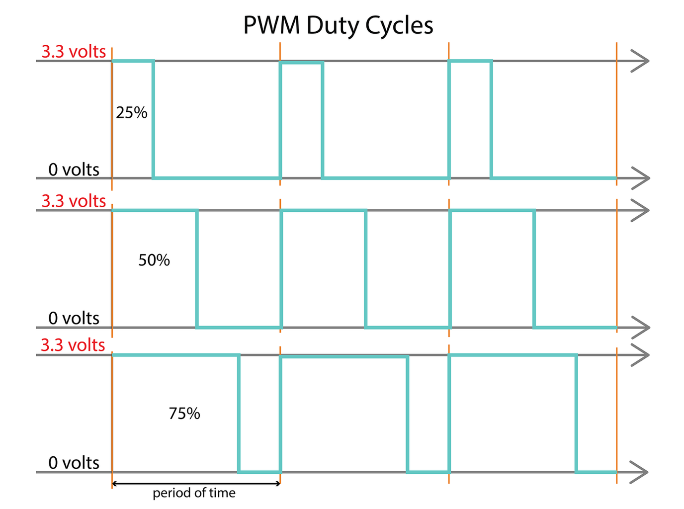
How Does it Work?
PWM pins can swing off (0V) and on (5V) at varying speeds. This on/off pulse creates a square wave. The width of the pulse in this wave is defined by a duty cycle. The duty cycle is how much the width of the pulse takes up a segment of time. Take a look at the graph, a 25% duty cycle takes up that portion of one time period, the same goes for a 50% and 75% duty cycle. A 100% duty cycle is on all the time and 0% is off.
Step 6: LilyPad Series

The LilyPad microcontroller was the first sewable board to hit the streets. It was developed by Leah Buechley and is produced by Sparkfun. It's designed to be used with fabrics and has championed the bridge between people that love hand crafts and the DIY electronic and programming communities.
The LilyPad's debut was in 2007 on Sparkfun.com and the microcontroller has had several versions made since then. There is also a growing series of accompanying sewable components. The series ranges from single colored LEDs to bluetooth modules to make your project wireless. To check out everything the LilyPad series has to offer, head over to Sparkfun.
If you want to learn more about Leah and the LilyPad board, read this Make: article focusing on its fascinating history.
Step 7: LilyPad USB
The LilyPad USB is the board you are using for this class and the most recent version of the LilyPad board. It has voltage regulation, a LiPo battery connector and can be used as a generic USB keyboard and mouse. All that is needed is a micro USB cord to upload a program. It uses the ATmega32u4 chip, rather than the ATmega328 that is used in the Main and Simple LilyPad boards. You can find all the hardware details on the Arduino hardware page.
Size and Pin Assignment
+ diameter: 2"
+ digital input/output: 9
+ PWM (analog output): 4
+ analog input: 4
Parts of the LilyPad USB (you don't have to study this, just keep it for reference)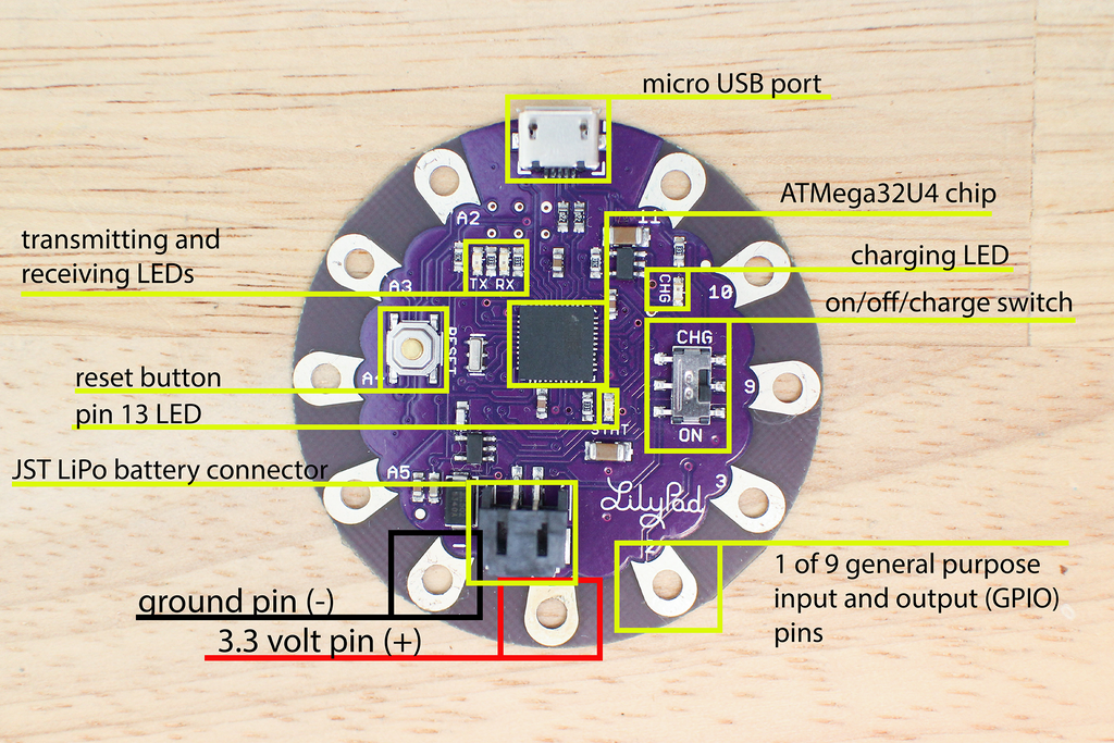
Step 8: Powering the LilyPad USB
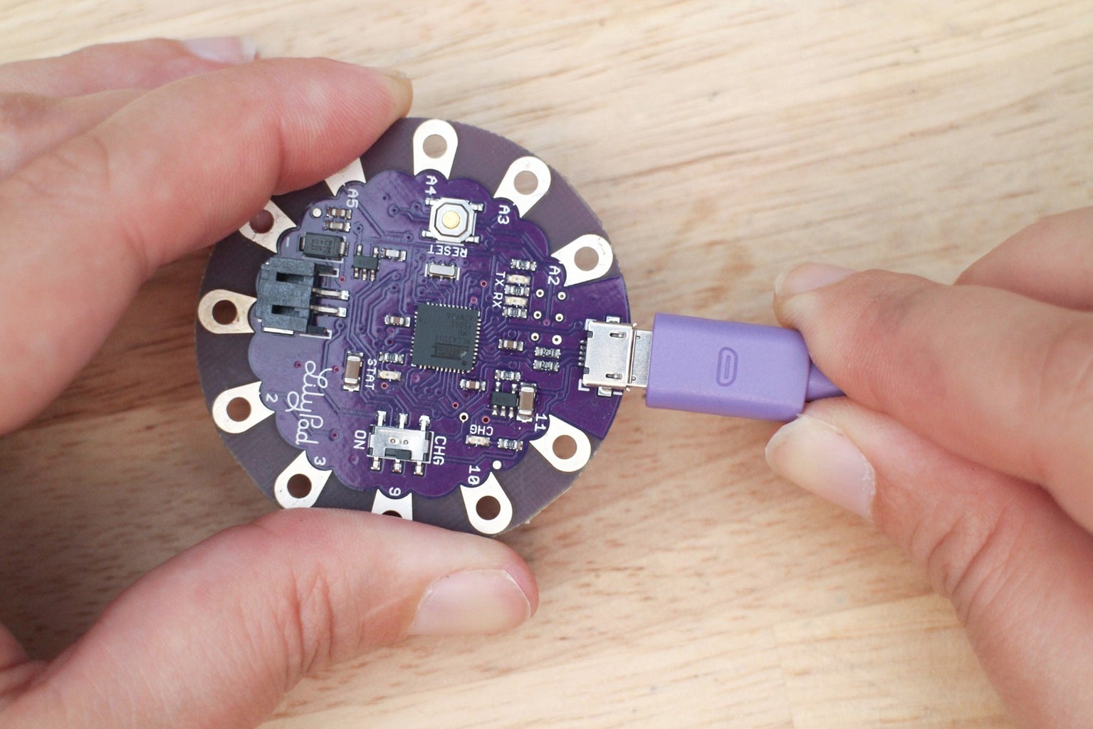
Micro USB Cable
When you are programming the LilyPad, the board is powered through the computer's USB port. The computer's port provides 5 volts which are regulated down to 3.3 volts. The maximum current you can draw is 500mA, which is more than you need for the LilyPad.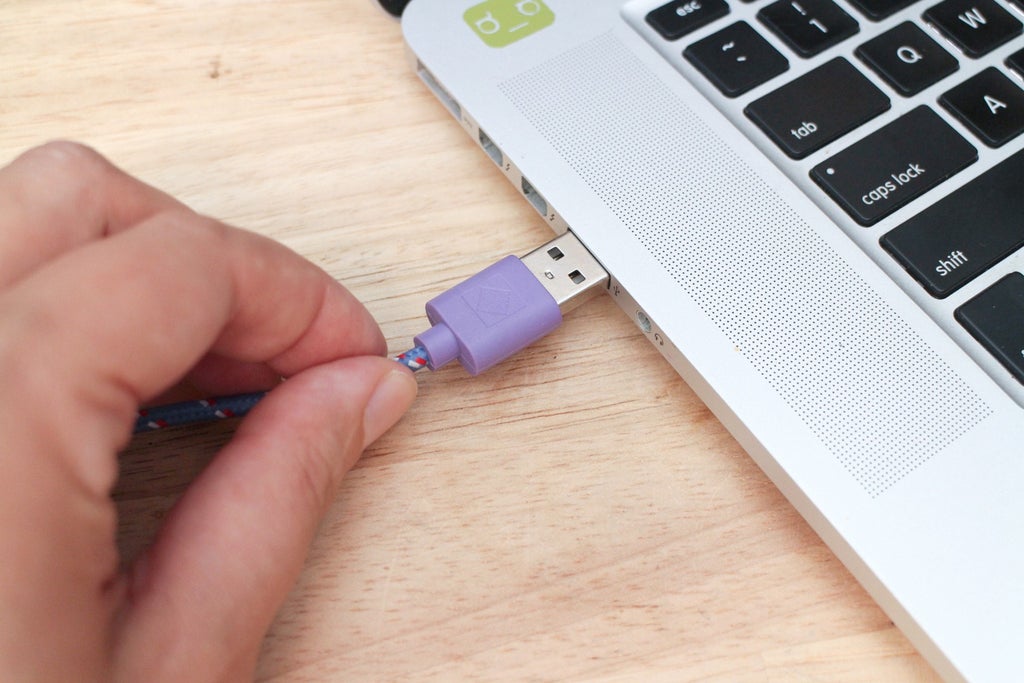
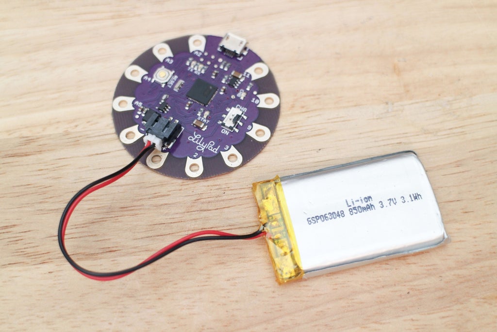
LiPo Battery
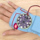
When the board is programmed, you can make your project mobile by using a battery for power. You can snap a rechargeable polymer lithium-ion (LiPo) battery into the JST connector on the board. Use a 3.7 volt LiPo battery, it gets regulated down to the board's operating power of 3.3 volts.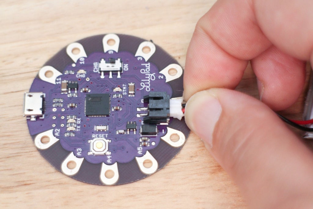
Power Switch
The LilyPad USB board has an on/off switch. When this switch is pushed towards CHG the board is off and does not get power, push it towards ON to power the board.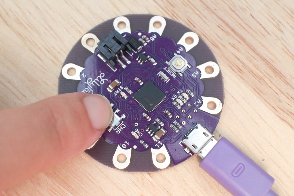
The LilyPad USB has a charging circuit. When a LiPo battery is plugged in and the board is plugged into the computer, push the switch towards CHG to charge the battery.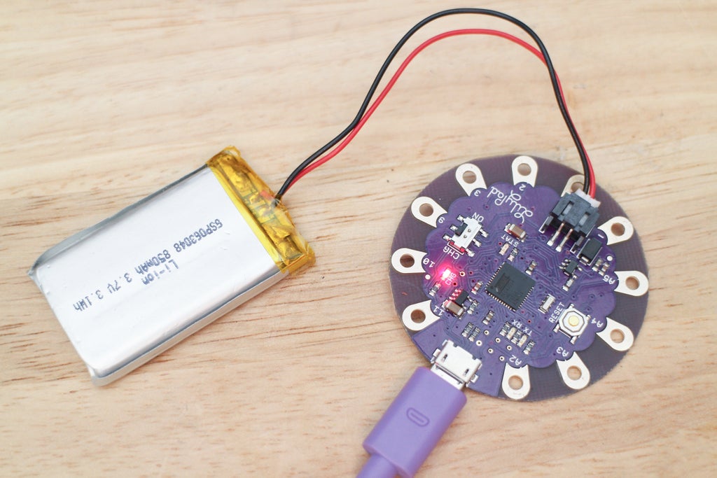
Step 9: Install Arduino on Your Computer

The software you use to upload programs to your board is the Arduino IDE (integrated development environment). These programs are called sketches and that's how I'll be referring to them during this class.
Go to Arduino's website and download the latest version of the Arduino software.
Extract and install the application onto your computer. Arduino's website has a LilyPad Arduino Getting Started page for Mac OS X and Windows that guides you on installing the software and additional drivers dependent on your computer's operating system. Head over there to get set up.
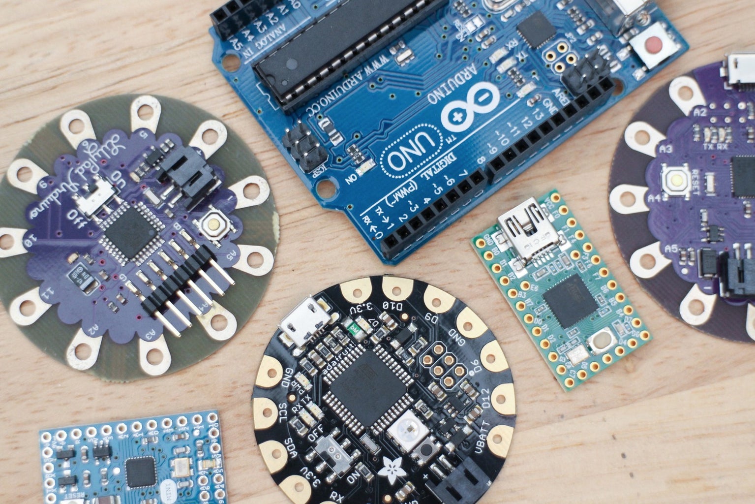
Step 10: What Else Is Out There?
The amount of microcontrollers available out there is impressive and can be a bit daunting. Read on to learn about some of the other boards I like to use for wearable projects. There is a whole DIY electronic world out there!
Step 11: Adafruit's Flora Platform

Adafruit is an open-source hardware company created by Limor Fried. The company introduced an official wearable electronics platform called Flora in 2012. You can read more about the release on their website. Some cool components that have come from the Flora platform are NeoPixels and a sewable GPS module.
Their wearable projects have been headed by Becky Stern, known for her Wearable Electronics youtube show using Flora components. The Flora and it's accessories are well documented and Adafruit offers many projects to learn from on their website.
Flora components are designed to be used with the Flora microcontroller specifically, but some components can be used with other boards using Adafruit's software libraries.
Step 12: Flora Microcontroller
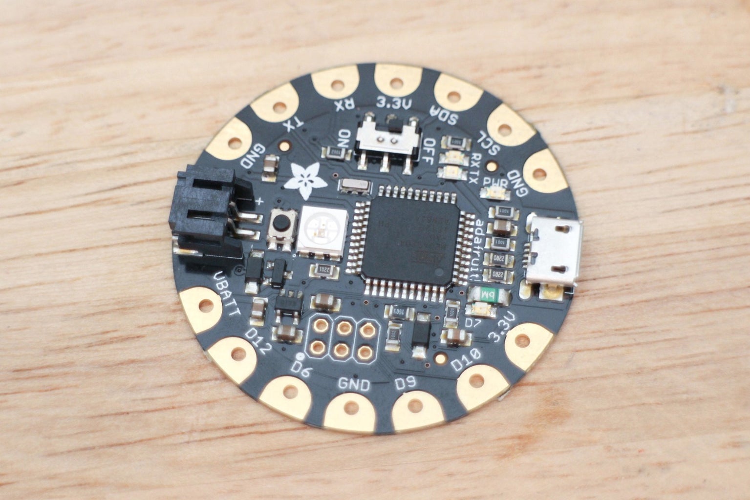
The Flora is built using the ATmega32u4 chip, like the LilyPad USB. Both are Arduino compatible. To use a Flora with the Arduino IDE, you need to install hardware support through the board manager. To use their components and sensors, they have many custom built software libraries to install and work with. This can easily be done by following the Getting Started with FLORA page Adafruit has put together.
Size and Pin Assignment
+ dimensions: 1.5"
+ digital input/output: 8
+ PWM (analog output): 4
+ analog input: 4
Step 13: Arduino Gemma

This is one tiny sewable microcontroller! It's perfect for those small accessories that don't need more than a couple inputs and outputs. It uses the ATtiny85 chip, has an on-board USB port to program with and a battery plug.
Size and Pin Assignment
+ dimension: 27.98mm (1.1") round in diameter
+ digital input/output: 3
+ PWM (analog output): 2
+ analog input: 1
Hardware page
Step 14: Arduino Mini
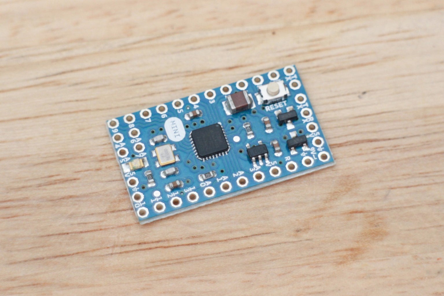
A microcontroller does not have to be sewable to be great for wearables. The Arduino Mini is a nice bite-sized microcontroller that has lots of pins and is Arduino compatible.
Size and Pin Assignment
+ dimension: 30mm x 18mm
+ digital input/output: 14
+ PWM (analog output): 6
+ analog input: 8
Hardware page
Step 15: Teensy 2.0

The Teensy is another favorite for wearable electronics. It's small, has tons of pins to use and can act as a USB keyboard and mouse.
To program it using Arduino, additional software needs to be downloaded called teensyduino. The download and install are very easy and well documented. Check out the Teensy's documentation site for tutorials and other boards to choose from.
Size and Pin Assignment
+ dimensions: 1.2" x .7"
+ digital input/output: 25
+ PWM (analog output): 7
+ analog input: 12
Hardware page
Step 16: Choosing a Microcontroller
Microcontrollers come in all shapes and sizes. Some are sewable, like the one you will use in this class, some have WiFi capabilities, some are large and some are small. In this class, you are using the LilyPad USB, which is a great intro board. You do not need to worry about choosing a board for this class. However, it's important to know that some boards will suit your project's needs better than others.
To choose which one is best for you, it's best to look at a board's features and what it is capable of out of the package. These features can be found on a board's hardware page, pinout diagrams you find online, and descriptions from the board's manufacturer.
Here are some basics to keep in mind if you would like to choose another for a future project.
1) Does the board have enough pins to support the digital and analog devices used in my project requires?
2) What power source will I be using and can the board support that? Just like components, microcontrollers are rated for voltage and current maximums. They also regulate and output a certain amount of voltage and current once powered.
3) Does size matter?
4) Do I need a board that can be an HID (keyboard or mouse)?
5) Am I making an instrument? Some boards are made specifically for holding more data, like sound files and some are able to output MIDI.
6) Do I need wireless support?
Step 17: Test Your Knowledge
{
    "id": "quiz-1",
    "question": "A digital signal has two states.",
    "answers": [
        {
            "title": "false",
            "correct": false
        },
        {
            "title": "true",
            "correct": true
        }
    ],
    "correctNotice": "That's correct",
    "incorrectNotice": "That's incorrect"
}
{
    "id": "quiz-2",
    "question": "A volume knob is an example of what kind of signal?",
    "answers": [
        {
            "title": "Analog",
            "correct": true
        },
        {
            "title": "Digital",
            "correct": false
        }
    ],
    "correctNotice": "That's correct",
    "incorrectNotice": "That's incorrect"
}
{
    "id": "quiz-3",
    "question": "Is an LED off or on when it is getting a PWM signal that has a 100% duty-cycle?",
    "answers": [
        {
            "title": "Off",
            "correct": false
        },
        {
            "title": "On",
            "correct": true
        }
    ],
    "correctNotice": "That's correct",
    "incorrectNotice": "That's incorrect"
}


