

Introduction: Introduction to the Lang Vise System


The Lang workholding system is a modular and precise workholding system that's great for a wide range of CNC projects, from the simplest to the most complex 5-axis part.
This lesson will cover the following:
--Advantages of the Lang workholding system
--An overview of the the four different Lang vises at Pier 9:
Small Makro 5-axis vise
Large Makro 5-axis vise
The Ino-Grip 3-Jaw Chuck
The Profilo vise with soft jaws
--How to install the vises on the receiver plate and how to hold the stock
--How to use the torque wrenches to attach the vises to the receiver plate and secure the stock
--How to flip the jaws on the Makro vises
--How to reconfigure the jaws on the 3-jaw chuck
Step 1: Advantages of Lang Vises
Lang's workholding system has three clear advantages:
1) Eliminate the need to establish a Work Coordinate System with a probe.
Inside the Matsuura and the Haas VF2, there are permanently installed Lang vise receiver plates. Each vise attaches interchangeably to the receiver plate in a repeatable and accurate position. The DMS stand also has a receiver plate, and this stand is always installed in exactly the same position with indicator pins.
Inside your CAM software, you will set your Work Home to the center top of the Lang receiver plate. The coordinates for these corresponding locations inside the machine are stored inside the the DMS as G159 N7, inside the Haas VF2 as G154 P1, and inside the Matsuura as G54. This means that as long as you choose the correct active coordinates in both your CAM software and the machine, you do not need to probe your stock at all, and you have perfect repeatability.

2) Ability to juggle multiple projects on the same machine quickly.
Projects can be swapped out on the machine easily. If you haven't finished your part, you can remove it while it's still inside the Lang vise, and then later put the vise back in the receiver plate and continue machining. As long as you never changed the part's location in the vise, you'll know that everything is perfectly registered.
3) Ability to move a project from one machine to the next with ease.
You can start a job on the Haas VF2, and then move it over to the Matsuura for final five-axis features. Again, as long as you don't move the part inside the jaws, you can move the vise from one receiver plate to the next and proceed with machining without needing to re-locate your part.
Step 2: Overview of Lang Vises

The four available vises at Pier 9 can be used interchangeably on any receiver plate, and are all installed in the same way.
In the chart above, the clamping range specifies how much stock can be held inside the jaws of that vise.
The maximum torque is the amount to set on the torque wrench when tightening the vise jaws around the stock.
Here are some additional specifics for each vise.
Makro vises:
--Jaws can face in or out, depending upon the size of the stock. Jaws must be facing out for the wider clamping range.
--Part can be installed "high" (held by 3 mm of clamping force, secured with small teeth that create indentations in stock) or "low" (held lower down with no teeth for a smooth finish).
 <="" p="">
3-Jaw Chuck:
--Jaws can be placed in four positions to accommodate different stock diameters.
--Jaws can face in or out.
--Part can be installed high or low as well.
 <="" p="">
Step 3: Attaching Lang Vises to Receivers
You will learn more about the specifics of installing vises in the machine lessons, but here is the general workflow for installing Lang vises on a Quick-point receiver plate, which is either rectangular (Haas Mill) or round (DMS and Matsuura). All four vise types can be used with any receiver plate, and are installed the same way.


--Clean the receiver plate and vise with a dry cloth to remove chips and debris.
Any chips trapped between the two can damage the vise and receiver plate, and can cause tolerances to decrease over time.
--If necessary, remove blue hole plugs by cupping your hand and using compressed air. For holes you will not need, replace blue hole plugs to prevent chips from getting inside the receiver.
--Ensure the 8 mm allen bolt in the front of the receiver plate has been turned counterclockwise enough to allow the vise to sit flat on the plate.
--Place clamping studs in the bottom of the vise inside the holes in the receiver plate.
Ensure the front of the vise is facing you. For the Makro vise, the front jaw will have the letter L, indicating that the threaded rod that closes the jaws will tighten the jaws when turned clockwise. The front jaw will also indicate the maximum torque, 100 N m. For the 3-jaw chuck, the front is indicated by the 10.9 mm square socket, which should be slightly left of center.

Step 4: Using Torque Wrenches
To secure Lang vises to receiver plates and to tighten stock, you will need to use torque wrenches to ensure that your gripping force is sufficient.
To secure the vise to the receiver plate, you will use an 8 mm allen driver on a torque wrench set to 30 N m.
--Use the torque wrench with the blue handle.

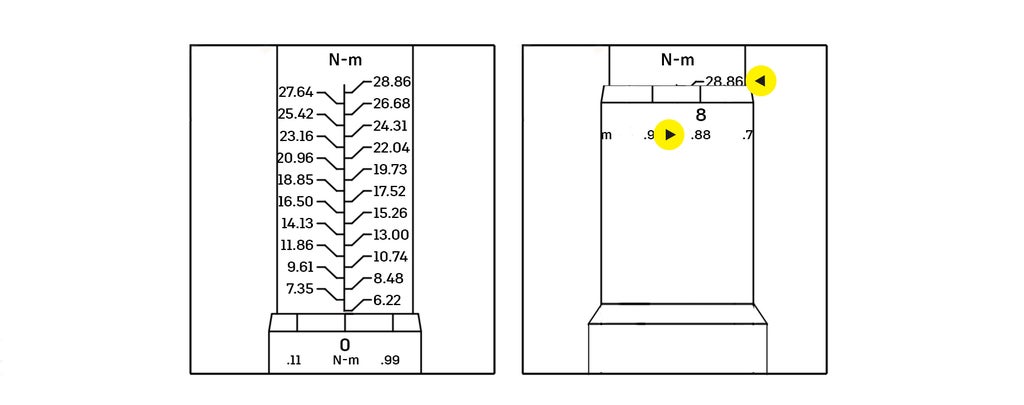
--Rotate the handle to set the torque to 30 N m.
Each tick mark in the vertical tree indicates a base torque value. The horizontal values on the handle that intersect the vertical line are added to this base value.
For example, to set 30 N m, turn the ring to the right as far as it will go. This will set a torque equal to 28.85 (base value) + .88 (ring value), or 29.73 N m. Confirm that you are looking at N m, not Ft lbs.
--Tighten until the wrench disengages with a clicking sound.

Once the vise is installed on the receiver, follow these steps to load rectangular stock on the Makro Vise:
--Center the stock in the vise jaws with the tick marks along the jaws.
--Use the 12 mm socket on the large torque wrench with the black handle.

--Pull the ring above the handle down and turn the handle to set the torque to 100 N m.
Use the base mark of 81.4 N m and the handle mark of 19 N m (the bottom row on the handle is N m).

--Tighten until the wrench disengages with a clicking sound.
Notice that if your part is "high" (held by 3 mm against the serrated edges), the clamping force will leave teeth marks on your stock. This helps hold the stock in position, and can be used as registration in case you need to remove your part from the vise.
Loosen with a regular wrench.

If you have installed the 3-Jaw Chuck on the receiver plate, follow these steps to load cylindrical stock:
--Center the stock in the vise jaws and place in the "high" or "low" position.
--Use a 10.9 mm square driver on the large torque wrench with the black handle.

--Pull the ring above the handle down and turn the handle to set the torque to 70 N m.
Use the base mark of 54.2 N m and the handle mark of 16.3 N m (the bottom row on the handle is N m).

--Tighten until the wrench disengages with a clicking sound.

Step 5: Flipping Makro Vise Jaws
The Makro vises accommodate rectangular stock. Use the small vise for stock up to 6" along the Y axis, and the small vise for stock up to 13.5" along the Y axis.
Here is an overview of the different jaw and part configurations:

Jaw Positions
Jaws In
Small Vise: Stock up to 3.5" between jaws (along the Y axis)
Large Vise: Stock up to 11" between jaws
Jaws Out:
Small Vise: Stock between 3.5-6" between jaws
Large Vise: Stock between 11-13.5" between jaws
Part Positions
Part High
Clamping distance of 3 mm
Use on unfinished surfaces (creates stamped impression in stock, but adds rigidity)
Part Low:
Use on finished surfaces
Jaws In: clamping distance of 10 mm
Jaws Out: clamping distance of 29 mm
Follow these steps to reverse the jaw orientation:
1) Open the jaws as far as possible, until they stop moving.

2) Carefully slide the jaws off the vise.

3) Flip the jaws, and fit back onto vise.
Each jaw is marked 'L' or 'R'. Match the letter to the corresponding side of the vise, also marked 'L' or 'R'.

4) Tighten the jaws. Apply pressure to both jaws to ensure that they engage the lead screw at the same time.
You may need an extra hand.

5) Tighten the jaws completely.
Jaws Out: If centered correctly, the jaws will both touch the vise's stop at the same time.
Jaws In: If centered correctly, the jaws will meet in the center of the vise.

6) Load the stock and clamp down with 100 N m of force.
Follow torque wrench instructions in previous step.

Step 6: Changing Lang Chuck Jaw Configurations
The Ino-Grip 3-Jaw Chuck can accommodate stock sizes up to 7" in diameter using the hardened gripping jaws.
Here is an overview of the different 3-jaw chuck configurations:
Jaw Positions:
Position 1 for stock up to 3" in diameter
Position 2 for stock between 2"-5" in diameter
Position 3 for stock between 3" - 6" in diameter
Position 4 for stock between 4" - 7" in diameter
Part Positions:
Use Part High against unfinished surfaces (creates stamped impression in stock, but adds rigidity)
Jaws In for clamping distance of 5 mm
Jaws Out for clamping distance of 10 mm
Use Part Low against finished surfaces
Jaws In for clamping distance of 21.5 mm
Jaws Out for clamping distance of 14.5 mm
To adjust or reverse the jaws in the 3-jaw chuck, follow these steps:
1) Using a 6 mm allen wrench, remove 6 mm screws from the jaws.

2) Using a 4 mm allen wrench, remove 4 mm screws from the base of the chuck that will be covered by the jaws.

3) Move jaws to new position

4) Secure jaws using 6 mm screws.
Insert 4 mm screws into open holes to prevents chips from getting inside.

5) Center stock and clamp down with 70 N m.
Use the 10.9 mm square-headed driver on the black handled torque wrench (54.2 N m on base, 16.3 N m on handle).
Loosen with a regular wrench.
Soft jaws can be used in place of the hardened gripping jaws to hold uniquely shaped work pieces or to match the geometry of a partially machined part. Because they leave no stamp marks, they are ideal for holding finished surfaces.

You should now have a general understanding of the software and hardware behind Workholding at Pier 9.
At this point in the class, navigate to the lesson that pertains to the machine you want to use.
Note that the video tutorials for the DMS and Haas Mill use the Makro vise(s) with rectangular stock, and the Matsuura video tutorials use the 3-jaw chuck with cylindrical stock. If you are using a machine-vise combination that is not covered, additionally watch the video tutorials from another lesson.
--Lesson 3: DMS five-axis Router
--Lesson 4: Haas Mill
--Lesson 5: Matsuura 5-axis Mill


