

Introduction: IoT Analog Input - Getting Started With IoT


Understanding Analog Inputs are a crucial part of understanding how things around us work, most if not all sensors are analog sensors (sometimes these sensors are converted to digital). Unlike digital inputs which can only be on or off, analog inputs can be anything from 0 to 1024 (depending on your microcontroller) which allows us to read a lot more data from sensors.
So in this project, we are going to take a look at how to read analog values with an IoT device and send the data back to our phone.
Step 1: Analog Vs Digital


Analog and digital both are quite different but both have their own uses. For example, all buttons are digital inputs, this is because digital inputs can only be 0 or 1, on or off, and as we know buttons can either be open or closed, again 0 or 1.
However, some inputs are a little more complicated than just a 0 or 1, for example, sensors send back a wide range of values which would be lost if you read them through a digital input but an analog input allows you to read values from 0 to 1024. This allows us to receive a lot more values.
An example of this can be seen in the provided pictures, the first photo shows a digital input, the value can only be 0 or 1 where the second value shows an analog input and as you can see it has a nice curve made with values between 0 and 1024.
Step 2: The Plan and What We Need

So of course in order to read analog values, we need some sort of sensor that spits them out. So we are going to be using a potentiometer which is a variable resistor this way we can see the values change as we move the knob.
We are also going to need to make an app for our phone to receive the values from the IoT board, however, this is done quite easily with AppSheds app builder.
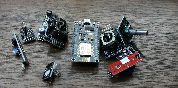
So to get this up and running we will need the following:
- IoT Board (We are using the NodeMCU but this is tested and working with the Sparkfun 8266 thing, Adafruit feather and generic ESP 8266 devices.
- A small potentiometer (anything from 50k to 500k will work fine)
- Breadboard
- Some male to male jumpers
The plan is to wire everything up on the breadboard, upload code to the Node and then connect it to our app that we will be making. Let's get started
Step 3: Installing the Libraries
to upload our code we are going to be using the very popular Arduino IDE which can be downloaded Here . Now because we are going to be using the website AppShed to control and edit the way the board works we don't need to focus on the actual code going into the board. The code we are uploading is the AppShed master sketch which allows the website to control all the pins on the board.
Now to be able to upload code to our board through the Arduino IDE we need to install its library which allows to IDE to talk to our specific board. This is done as follows:
Launch the Arduino IDE
Navigate to File and click Preferences
Towards the bottom, you should see "additional boards manager URLs" followed by a blank space
Copy and paste this into the blank space http://arduino.esp8266.com/versions/2.4.1/package_esp8266com_index.json
Now we need to install the boards under board manager.
Navigate to Tools, then Board and then Click on Board Manager
Now in the search bar search for ESP8266
Click on the first option and click Install
Now our board is able to communicate with the Arduino IDE
Step 4: Uploading the Code

So at this point, we have downloaded the libraries that are needed to help the Arduino IDE communicate with our IoT board and we've downloaded the libraries that allow the AppShed master sketch to run. Now, all we need to do is change the name and password of your IoT device in the code if you don't do this your IoT devices wifi name will be "Your_device_name_here".
To do this we need the following:
Plug your IoT board into your computer
Download and open the Appshed master sketch (which can be found here)
Navigate to tools and click on board
Scroll down until you see your board, then click on it (I'm using the NodeMCU so I'm going to click on NodeMCU)
Now navigate back to tools and click on port, from here you should see your board (should look like this "com 9" if you're on windows and "/dev/cu.wchusbserial1410' for mac)
Click the side facing arrow to upload and wait while it does so.
If you get a message after about 2 - 3 minutes saying done uploading then everything worked perfectly! To double-check that our board is working we can also go our WiFi setting and look for the name that we gave the board earlier if it's there it's working.
Step 5: Setting Up Our App
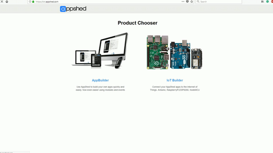

So before we can make the app we need to tell the website AppShed which pin on the board we are going to be reading from. To do this we head over to www.appshed.com and log in, once logged in you should see a page called IoT builder we are going to need to click on that.
Once inside the IoT builder, we start by creating a new board and naming it "IoT Input" followed by saving. At this point we are presented with a microcontroller with a lot of pins around it, these pins are representations of the pins on your IoT board. So for example, if we set pin 1 on this board to HIGH, pin 1 on your board will also go HIGH.
Now under Analog Inputs, you should see the option for a potentiometer, we are going to click on that and then click on pin 40 to link the pot to pin 40. Pin 40 represents pin A0.
With that linked we can click save and head over to the app building side of things
Step 6: Making the App


On the app building page, the very first thing you should be presented with is a simulated phone, the first thing we are going to want to do is to click the little plus icon at the bottom of the screen to start a new app.
Once the new app is loaded we are going to link the board we just made in the IoT builder, we do this by clicking on boards and then clicking on the board we just made. With this now linked we can head over to the forms field and click on the input box. We are going to give the input box the name "IoT Input" and we have to be sure to give it the exact same variable name as we gave the potentiometer in the IoT builder so make sure you put "pot" in the variable name field as this will link the IoT board to the input box.
Once we've clicked save the app is done! To get it onto our phone we can publish and once that done we can head over to share and click on QR code which we can scan with our phone.
Step 7: Wiring and Connecting

So now the last thing we need to do is connect our potentiometer to our IoT board and then connect our IoT board to our phone.
So connecting our pot to our IoT device is really simple all we need to do is connect the middle pin of the pot to A0 on the IoT board then we connect the left pin of the pot to 3.3 volts and finally we connect the right leg of the pot to ground on our IoT board.
Now to connect our IoT board to our phone all we need to do is connect your phone to the IoT boards wifi which should be really easy to find since we gave it a custom name in the code setup. (if you didn't give it a custom name the default wifi name is YourDeviceName and the password is YourDevicePassword). Once the devices are connected we can head back to the web app and you should see the values start streaming in.
Step 8: Taking It Further!
So in this project, we have learned how to send back raw data from a sensor to our phone, now in its current state this isn't too useful however imagining plugging in a sensor and setting your app to do something when the sensor reaches a certain value - things get a lot more interesting
Thank you so much for viewing as always if you have any questions we will be available in the comments to help out.


