

Introduction: Jasper the Arduino Hexapod


Project Date: November 2018
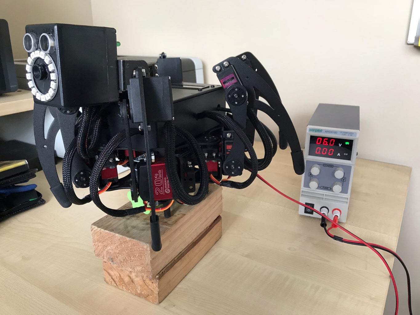
OVERVIEW (JASPER)
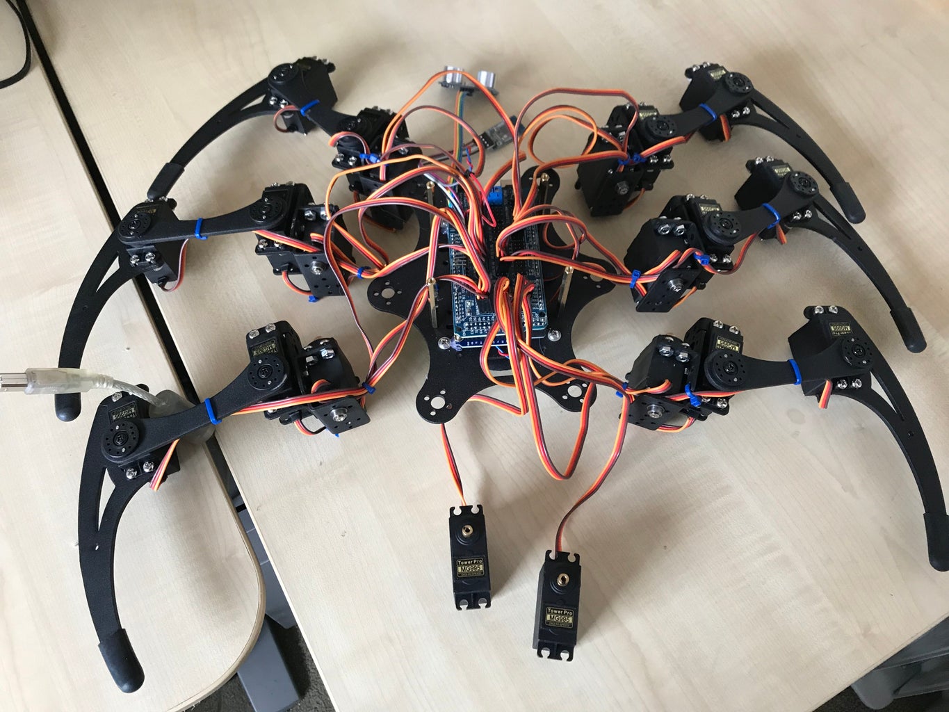
Six leg, three servo per leg, 18 servo movement system controlled by an Arduino Mega. Servos connected via Arduino Mega sensor shield V2. Communication with Hexapod via Bluetooth BT12 module talking to bespoke Android application. System powered by 2 x 18650, 3400mAh, and 2 x 2400mA battery set each held with Velcro under the body of the hexapod. A power toggle switch for both the Servo and Control systems is provided as is a green led power on indicator light on the head of the hexapod. Commands are repeated to a 16x2 LCD display. Video feed, light ring, and ultrasonic obstacle avoidance are located in the head.
NOTE: For the sake of sanity I highly recommend the use of good quality servos, I started with MG995 servos, 20 of them, 11 of which either burned out, lost the ability to centre, or simply stopped working.
Step 1: EQUIPMENT


1. 20 x DS3218 servos
2. 1x Hexapod base kit
3. 1x Arduino Mega R3
4. 1x Arduino Mega sensor shield v2
5. 1 x 2 bay 18650 battery holder
6. 2 x two pole power switch
7. Green led light and 220kohm resistor
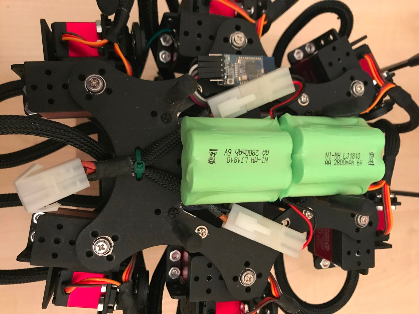
8. 2 x 6v 2800mAh battery packs with Velcro fixing
9. 2 x 18650 x 3400mAh batteries
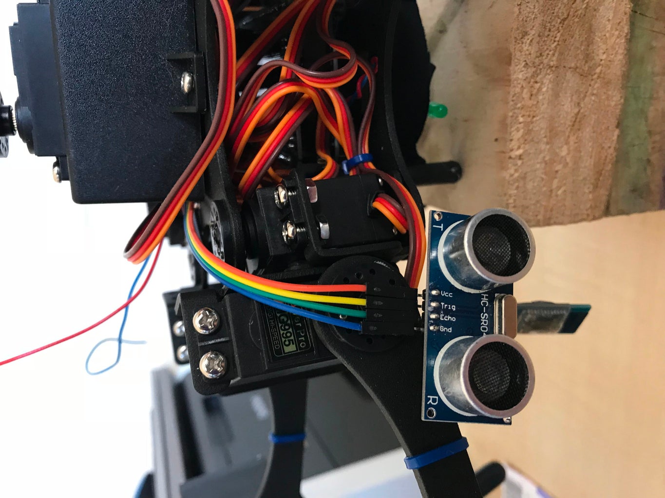
10. 1x HC-SR04 Sonar module
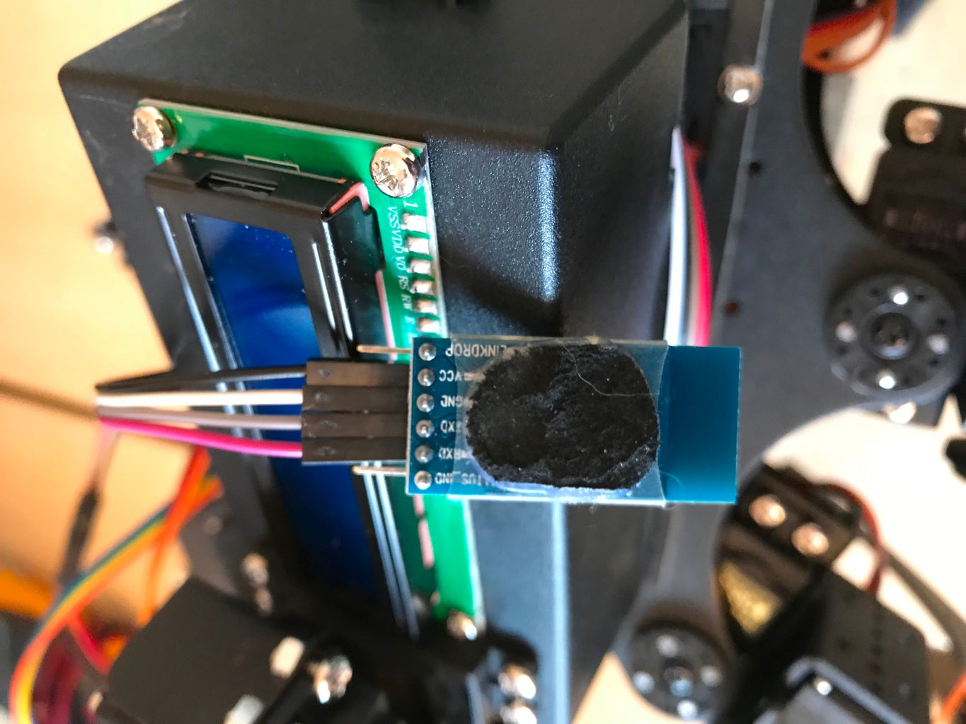
11. 1x BT12 Bluetooth module
12. 1 x Arduino V3 NodeMcu Lua WIFI ESP8266 12E IOT development board
13. 1 x Arducam Mini Module Camera Shield with OV2640 2 Megapixels Lens
14. 1 x Pixie Neon 16 LCD light ring
15. 1 x 16x2 line LCD display with attached IIC adapter.
16. 1 x 5v power plug for Arduino Mega
17. 1 x 5v micro USB plug for NodeMcu module.
18. 1 x DC to DC Buck converter module
19. 1 x 70mm x 120mm x 39mm square black plastic box (Body)
20. 1 x 70mm x 50mm x 70mm black plastic box (Head)
21. 4 x 40mm of M3 brass stand offs plus 4 rubber rest supports
22. Various male to male jumper cables, solder, m3 screws and bolts, and, hot glue
Movement of legs using bespoke logic. Camera movement via two independent servos giving up, down, left, right and centered movement. Camera controlled by WIFI connection, being displayed on WebView view in Android Application.
Step 2: SERVOS


Each has maximum 180 degree to
minimum 0 degree movement.
Each servo identified with three number combination, LegCFT; where C is the body(COXA), F is the thigh(FEMUR), and T is the elbow(TIBIA), so 410 would refer to the fourth leg and Tibia servo, similarly 411 would refer to the fourth leg and Tibia servo. Numbering sequence would be 100 through to 611. Each servo leg to have rubber-based foot to cushion impact and to provide better grip.
Leg 1: 100,110,111 Front
Leg 2: 200,210,211 leg2—leg1
Leg 3: 300,310,311 leg4—leg3
Leg 4: 400,410,411 leg6—leg5
Leg 5: 500,510,511 Back
Leg 6: 600,610,611
Default position for all Coax Servos is 90 degrees.
Default position for Femur Servos is 90 degrees, 45 degrees is the rest position.
Default position for Tibia Servos for all legs is 90 degrees, legs 1,3, and 5 use 175 degrees as the rest position and legs 2,4, and 6 use 5 degrees.
Neck 1: 700 Limited to 75 to 105 degrees for up and down movement
Neck 2: 800 Limited to 45 to 135 degrees for left and right movement
Servo movement limited to three “writes” before a 10-millisecond delay is included, before further “write” commands are issued. This helps to reduce the load on the batteries.
Step 3: COMMANDS


A=Stop – Stand in default position.
B=forward - walk_forward
C=reverse - walk_backward
D=right - turn_right
E=left - turn_left
F=left sideways movement - crab_left
G=right sideways movement - crab_right
H=Rear_crouch (legs 1 and 2 at maximum, 3 and 4 legs at neutral position, legs 5 and 6 at minimum position)
I= Front_crouch (legs 1 and 2 at minimum position, 3 and 4 legs at neutral position, legs 5 and 6 at maximum position)
J= camera cantered – center (Neck 1 and Neck 2 at mid position, default position)
K=camera left - pan_left (Neck 1, mid position, Neck 2 servo minimum position)
L=camera right - pan_right (Neck 1, mid position, Neck 2 servo maximum position)
M=camera up - pan_up (Neck 1 maximum position, Neck 2 servo mid position)
N=camera down - pan_down (Neck 1 minimum position, Neck 2 servo mid position)
O=Resting (Hexapod) sits on supports.
P=Standing Up – Hexapod stands up to the default position.
Q=Lights off
R=Green light on Pixie Neon light ring.
S=Red light on Pixie Neon light ring.
T=Blue light on Pixie Neon light ring.
U=White light on Pixie Neon light ring.
V=Front legs waving.
W=Sound Horn.
X=Sweep head from left to right.
Y=Play Tune.
Step 4: MOVEMENT


The Coax servo position is longitudinal to the axis of the body so straight ahead is 0 degrees and directly behind is 180 degrees. However, this Coax and all other servos would be limited to 45 through 135 degrees.
Leg movement of forward, reverse, left and right would all be started with the lifting of the leg using the Femur and Tibia servos, then followed by the body servo movement, and finally the lowering of the same leg again using the Femur and Tibia servos.
Forward and Reverse
To move forward or backward legs work in pairs, 1 and 2, 3 and 4, 5 and 6. A simple forward movement consists of legs 1 and 2 moving from their current position to as far forward as possible, then legs 3 and 4, and finally 5 and 6 legs repeat the same action. Then all six Coax servos move from this extended forward position back to their original starting position. The reverse of this process is used to move rearward. As part of the forward movement process the HC_SR04 ultrasonic unit will check for obstacles ahead and if one is found turn the Hexapod either left or right randomly.
Left and Right
To move left or right leg pairs work together but in opposite directions. So, for example to turn right leg 1 moves from the current position back to the 135 degree position while leg 2 moves forwards to the 45 degree position. This is repeated for leg pairs 3 and 4, and 5 and 6 legs. At which time the Coax servos move their original position back to their new position in so doing twisting the body into the direction of movement, I.e. right. This process is continued until the required rotation to the left has been completed. The reverse of this process is used to turn left, so leg 1 moves from its current position forward to the 45-degree position, while leg 2 moves backward to the 135-degree position.
Stand up and Rest
Both these processes don't use the Coax servo of any of the legs, so to stand up the Tibia servo, for all legs, moves from its current position to its maximum 45 degrees, while to rest these same Femur servos move to their lowest position, 175 or 5 degrees. The same movement applies to the Tibia servos which move to their maximum of 45 degrees, for standing, and their minimum, I.e. 175 or 5 degrees for rest.
Crouch Forward and Crouch Backward
Here again the processes are mirror images of each other. For crouching forward, legs 1 and 2 are at their lowest position, while legs 5 and 6 are at their highest position. In both cases legs 4 and 5 assume a neutral position which is in line with legs sets 1 and 2 and 5 and 6. For crouching backward legs 1 and 2 are at their highest position while legs 5 and 6 are at their lowest position.
Step 5: HEAD CAMERA/SONAR


The head will consist of a square plastic box 38mm x 38mm x 38mm with a removable lid. The box/head will have limited vertical and horizontal movement. Movement will be achieved by use of two servos, one attached to the body of the robot and a second attached to the first servos body and its arm attached to the head. 7.4v supplied by two 18650 batteries will power the Arduino V3 NodeMcu Lua WIFI ESP8266 12E IOT development board DEVKIT, attached to an Arducam Mini Module Camera Shield with OV2640 2 Megapixels Lens. This arrangement will allow the robot to detect obstacles and to stream live video via the on-board Wi-Fi. Sonar using a HC-SR04 and possible light management information would flow back to the Arduino Mega.
My thanks to Dmainmun for his Arducam Instructables article, which was of great help in my initial understanding of how the Arducam could be used to video stream.
Battery
It was decided to use two battery packs, one for the head's components and Arduino Mega board, and a second pack to supply power to all the servos. The first pack consisted of 2 x 18650 3400mAh batteries supplying 7.4v. The second pack consisted of 2 x 6V 2800mAh battery packs connected in parallel thus giving a 6.4V supply but increased capacity of 5600mAh attached to the underside of the Hexapod using Velcro strips.
Step 6: LEG MOVEMENT

Arms can either work in pairs or singly. Each arm consists of body joint called a Coax with 45 to 135-degree movement, a thigh joint called Femur, with 45 to 135-degree movement, and finally an elbow joint called Tibia, or end effector, with 45 to 135-degree movement. Bespoke software was written to provide the movement of the legs.
Types of leg movement:
For the Coax, 45 degrees is facing backward from the head, 90 degrees is neutral position, and 135 degrees is facing forward.
For the Femur, 45 degrees is highest position from the ground, 90 degrees is neutral position, and 135 degrees is lowest position from the ground.
For the Tibia, 45 degrees is most distant position from body, 90 degrees is neutral position, and 135 degrees is nearest position to body.
Assume that all servos are at the neutral position, 90 degrees.
Forward: Leg 1 and 2, Femur lift to 135 degrees, Coax moves to 45 degrees, Tibia moves to 45 degrees most distant from body, Femur lowers to 45 degrees. This is repeated for leg pairs 3 and 4, and leg pair 5 and 6. All 6 Coax servos move from 45 degrees backwards to 90 degrees, neutral position, all 6 Femur servos move from 45 degrees up to 90 degrees, neutral position. Finally, all Tibia servos move up from 45 degrees to 90 degrees, neutral position.
Reverse: Starting with legs 5 and 6, then 3 and 4, and finally legs 1 and 2, otherwise movement is the same for Coax, Femur, and Tibia.
Left: Legs 1,3, and 5 move in reverse direction, while legs 2, 4, and 6 moves in a forward direction. Both forward and reverse movement conform to the standard forward and reverse movement. To complete the turn all six Coax servos, move 45 degrees which turns the body.
Right: Legs 2,4, and 6 moves in reverse direction, while legs 1,3, and 5 move in a forward direction. Both forward and reverse movement conform to the standard forward and reverse movement. Coax movement is similar to above but in the reverse direction.
Rest: All Coax and Femur servos in neutral position, all Tibia servos in lowest position 45 degrees, effectively crouching both front, middle, and rear legs.
Crouch rear, stand front: Legs 1 and 2 at highest position, legs 3 and 4 at neutral, and legs 5 and 6 at lowest position.
Stand rear, crouch front: Legs 1 and at lowest position, legs 3 and 4 at neutral, and legs 5 and 6 at highest position.
Crab left: Legs 1 and 5 lift and extend outward to the left, at the same time legs 2 and 6 lift and contract under body. With all four of these legs on the ground all Tibias return to their neutral position. Finally legs 3 and 4 repeat the same process.
Crab right: Legs 2 and 6 lift and extend outward to the right, at the same time legs 1 and 5 lift and contract under body. With all four of these legs on the ground all Tibias return to their neutral position. Finally legs 3 and 4 repeat the same process.
Left head movement: neck 1 servo 45 degrees. Both servos return to 90 neutral position.
Right head movement: neck 1 servo 135 degrees
Up head movement: neck 2 servo 45 degrees
Down head movement: neck 2 servo 135 degrees
Pan head movement: neck 2 moves from 45 to 135 degrees
SERVOS
After initial testing the MG995 and MG996 servos where all replaced. All 20 servos where replaced with DS32228 20kg servos which provided much improved centring and increased load capacity.
It is important to thoroughly test each servo using a suitable test program. I modified the simple “sweep” example program to specifically test for 0, 90, and 180 positions, this test routine was run for a minimum of 5 minutes for each servo and then repeated a day later.
NOTE: Using a standard Arduino Uno board powered by a USB cable may not provide enough voltage to run certain servos. I found that the 4.85v the servo received from the Uno caused erratic behaviour with the DS3218 servos, increasing this voltage to 5.05v cured this problem. So, I decided to run the servos at 6v. In the end I found that a voltage of 6.4v was necessary as the 6v caused erratic behaviour of the servos.
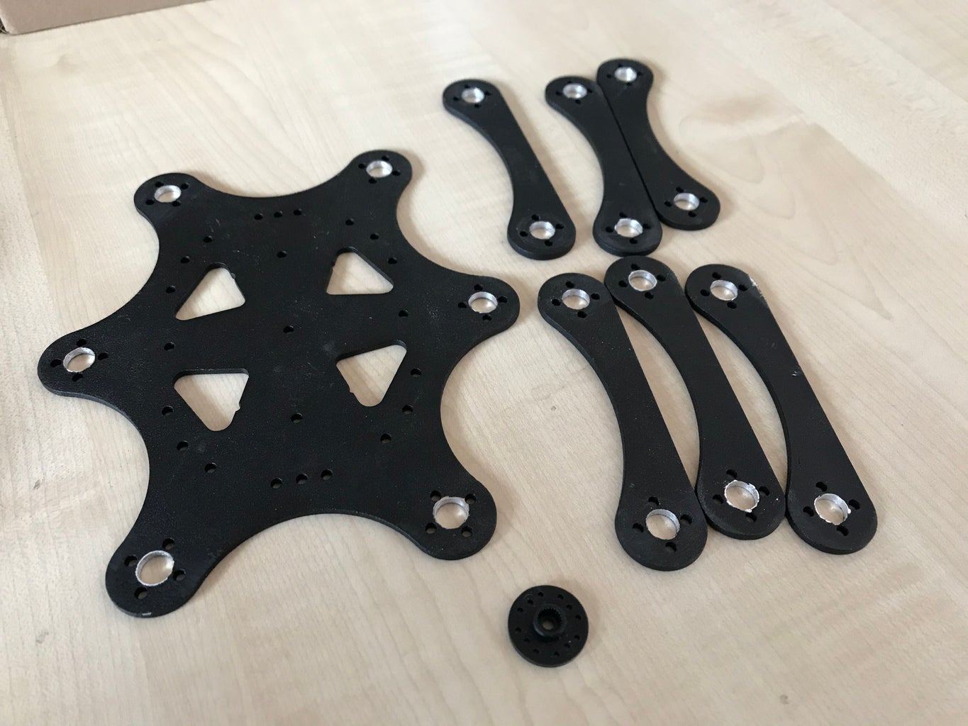
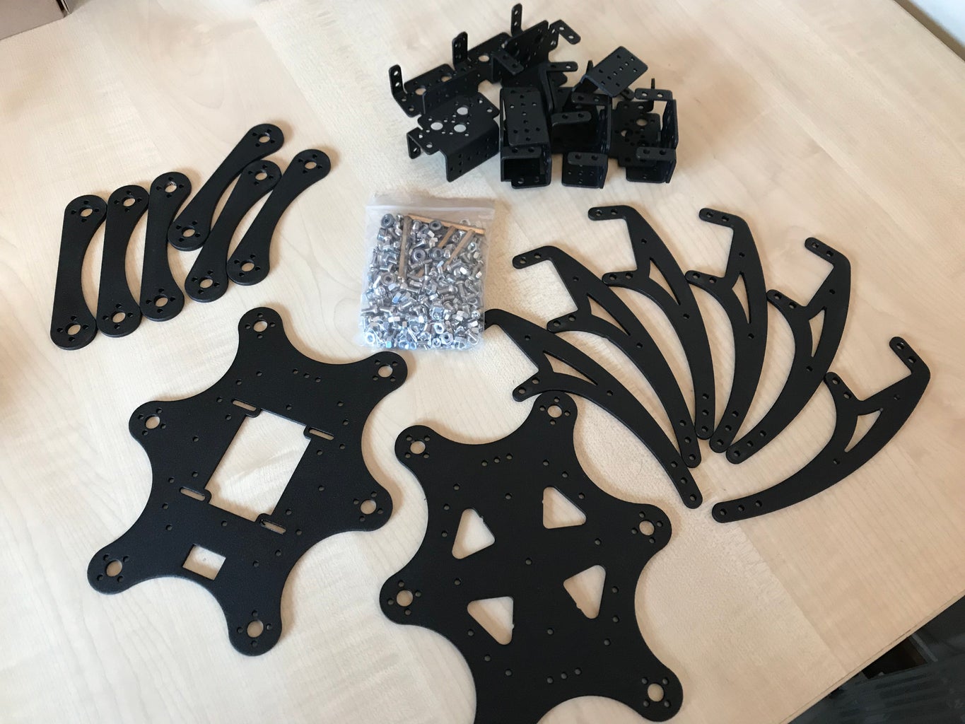
Step 7: CONSTRUCTION


LEGS
Started with the laying out of the Hexapod kit parts. All servo circular horns required the enlarging of the matting hole in both ends of the Femur and all Coax holes. Each servo horn was attached to its corresponding Coax and Femur with four screws and a fifth screw through the centre of the servo head. All servo bodies where attached using four bolts and nuts. The Coax servo mount, for each of the six legs, had a bearing attached to the bottom of the mounting using a single bolt and nut. Each Coax servo mounting was attached, using four bolts and nuts, to its Femur servo mounting with this mounting being rotated 90 degrees. The head of the Femur servo was attached to one end of the Femur arm with the other end of the Femur attached to the Tibia servo head. The six Tibia servos were attached to the top of the six legs with four bolts and nuts. Each leg end effector was covered with a soft rubber boot to provide extra grip. It was found that the supplied servo horn was too large to fix into the Coax, Femur, and Tibia connections so all centre holes were enlarged to 9mm. My thanks to “Toglefritz” for his Capers II instructable regarding the construction elements of the Hexapod kit. I did however deviate from the construction in one area namely the attaching of the servo horns to both ends of the Femur. I decided to enlarge the centre hole of the Femur to allow the centre of the servo horn to pass through it hereby giving the servo horn extra strength as it was closer to the servo and these two joints experienced the maximum torque. Each servo horn was attached to the Femur using two M2.2 self tapping screws, the ends of these screws being removed and filed flat. All M3 bolts had lock tight applied.
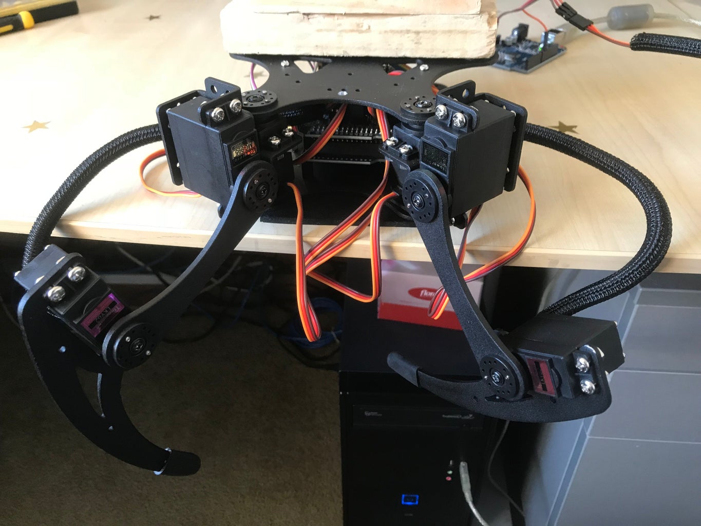
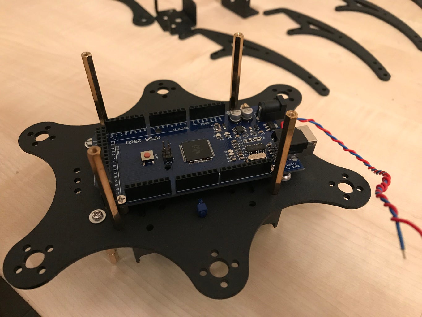
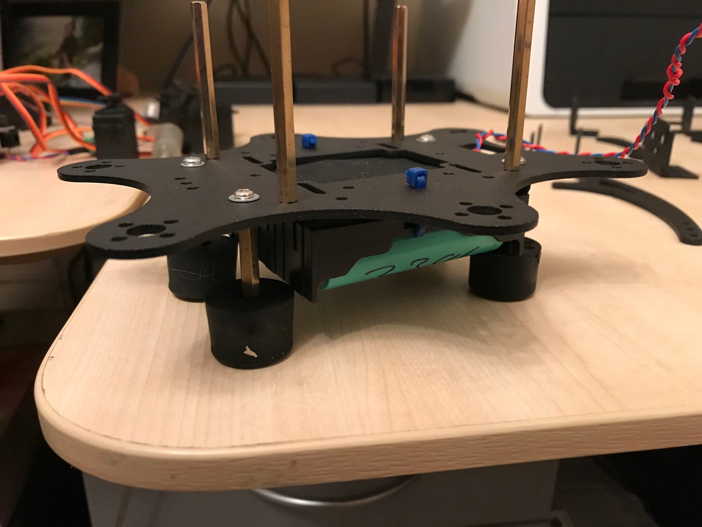
BODY
The body consists of two plates each with six holes, each hole used to attach the Coax servo horn. Two 6V 2800mAh batteries was attached to the underside of the bottom plate using Velcro. Four M3 stand offs extending just past the bottom of the battery holder were attached, each having a soft rubber boot slid onto the bottom, this provides a stable base onto which the Hexapod can rest. The upper section of the bottom plate has the Arduino Mega and its Sensor shield attached using four 5mm stand offs. On the top of the bottom plate was attached 4 x M3 stand offs 6cm in height, these surrounded the Arduino Mega and provided support for the top plate. The top plate had a 120mm x 70mm x 30mm box attached to it, this will house the first of the neck servos, and LCD screen. A second 2 bay, 2 x 18650 battery holder was attached to the underside of the top plate to the rear of the Arduino Mega board facing towards the front of the Hexapod.
The top plate has six servo horns each attached with four M2.2 screws. Onto the top of the plate is installed a 70mm x 120mm x 30mm box into which a 2 bay 18650 battery holder, two pole switch, green LED, and an IC2 16 x 2 LCD display are installed. In addition, the first neck servo is also installed, power and the second neck servo data cable pass through a hole to feed the second servo and Arduino V3 NodeMcu module. A further data cable passes through the top box and feeds the HC-SR04 ultrasonic module, again located in the head. A second data and power cable is also past to the head to power the pixie led ring.
The two servo data cables and the HC-SR04 data cable are fed through the top plate while the Bluetooth module is attached to the underside of the plate using a neon form pad and hot glue. Cable management of the remaining 18 servo data cables must be in place before any attempt to fix the top plate to the bottom plate using 4 x M3 screws which fit into the 4 x M3 stand offs which were attached to the bottom plate. As part of the top bottom plate attaching process all six Coax servos must also be placed in their correct position with the bearing fitting into the bottom plate hole and the servo head fitting into the top plate horn. Once fitted the tops of the six Coax servos are secured with 6 M3 screws. Due to the position of the servo horns for the six Coax servos the 4 x M3 stand offs needed to be reduced in height by 2mm, so that the Coax servo bearings sat correctly in the bottom plate.
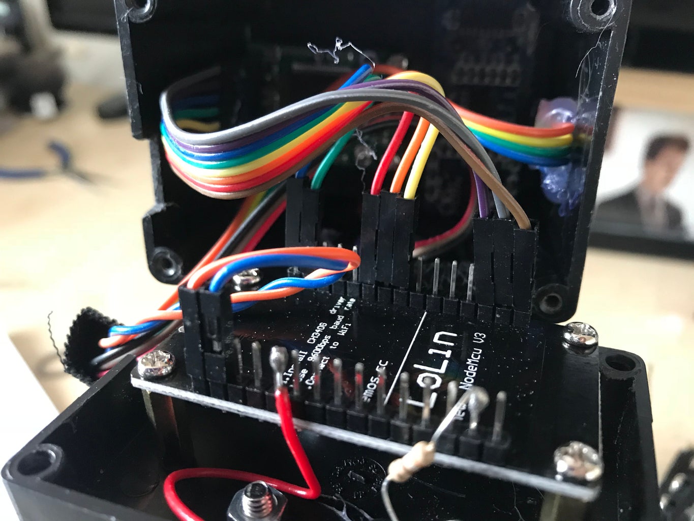
HEAD
The head consists of two servos 90 degrees to each other, one housed in the box attached to the top plate, and the second attached to the first via the servo horn using a U-shaped section of brass plate. The second servo’s horn is attached to an L shaped brass bracket which is itself attached to a 70mm x 70mm x 50mm box with two bolts and nuts. The box forms the head, inside of which is installed the Ardcam camera, HC-SR04 ultrasonic module, and the Arduino V3 NodeMcu module, and power LED. Both the ultrasonic module transmits and receive sensor heads protrude through the front of the box as does the camera lens. Surrounding the lens on the outside of the box is a 16 LCD Nero pixie ring. The NodeMcu power LED is seen via a hole in the back plate of the head, power cable, data cable of ultrasonic module, and pixie Neon data power cables enter via a hole in between the back plate and head plate.
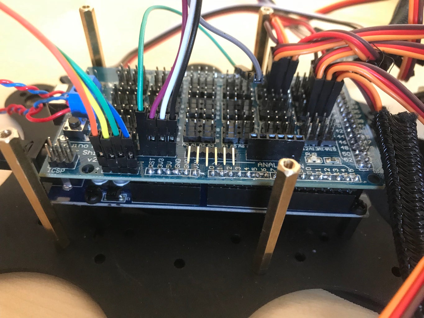
ELECTRONICS
The following Fritzing diagrams shows the body and head electronics. The VCC and GRD lines are not shown for the 20 servos to aid clarity of the diagram. The Bluetooth module, via the Android App., controls the Hexapod movement including its neck servos. The WIFI based Arduino NodeMcu module controls the Arducam camera module. All servos are attached to the Arduino sensor shield via a single block containing VCC, GRD, and signal lines. Standard 20cm DuPont jumper cables are used to connect the Bluetooth BT12, HC-SR04, and IC2 LCD.
LEG CALIBRATION
This is one of the most difficult areas of preparation prior to work on the movement of the Hexapod. The initial idea is the set all legs to the following, Coax servos 90 degrees, Femur servos to 90 degrees, and Tibia servos set to 90 with the physical leg position set to 105 degrees for legs 2,4, and 6, and 75 degrees for legs 1, 3 and 5. The Hexapod was placed on a level surface resting on the four supports underneath the battery housing. It’s legs where positioned at equally distance points between each leg and at equal distance from the body. All these positions where marked on the level surface. During the construction of the legs the middle point of each servo was found, this should be the servos 90-degree position. This 90-degree default position is used with all servos.
Coax servos 2 and 5 inner faces are parallel with each other, this goes for servos 1 and 6, and 3 and 4. All Femur and Coax servos are fixed together at 90 degrees to each other during the construction phase. All Femur servos have the Femur arm attached to them at a 90-degree angle. All Tibia servos are attached to the Tibia at 90 degrees. 2,4, and 6 Tibia servos are attached to the Femur arm at 105 degrees, while Tibia servos 1,3, and 5 are attached to the Femur arm at 75 degrees.
It is important to note that while testing, all servos should be monitored for temperature, a hot servo means the servo is working too hard and could fail, most servos will be warm to the touch.
The initial calibration is to move the Hexapod from its resting position, after being switch on, to a standing position which is both steady, stable, level, and most importance none of the servos are over heating. In order to maintain a steady position, it is necessary to write to each servo with a delay less than 20 milliseconds, 10 milliseconds were used. All servos can only move from 0 to 180 degrees and from 180 degrees back to 0, so for all Femur servos 0 and 180 degrees is vertical and 90 degrees is horizontal.
Prior to attaching each servo an initialization write was sent to each of the previously defined servos giving it its current angle of rest, I.e. the current position the servo is in while resting. This was 90 degrees for all Coax servos, 55 degrees for Femur and Tibia servos 1,3 and 5, and 125 degrees for Femur and Tibia servos 2,4, and 6.
It is important to note that batteries should always be fully charged at the start of the calibration session.
The Hexapod always starts from a resting position, the entire body being supported by the four feet. From this position all Femur and Tibia servos are cycled from their start positions up to their standing position, at which point all servos are at 90 degrees. To complete the standing position the “stand” command is issued this command requires all legs to lift up and set down again in two sets of three leg movements, legs 1,5, and 4, and 2,6 and 3.
Step 8: SOFTWARE
The software consists of three parts, part one is the Arduino code that runs on the Arduino Mega, part two is the Arduino code running on the NodeMcu module in the head. Communication is via the Bluetooth BT12 unit which receives commands from the Android tablet, namely a Samsung Tab 2, which is running an Android Studio built custom application. It is this application that sends commands to the Hexapod. The same application also receives live video feed from the NodeMcu module via its built in WIFI.
ANDROID CODE
The bespoke Android code, developed using Android Studio, provides the platform onto which the two screen application is run. The application has two screens, the main screen allows the user to issue commands to the Hexapod and view the video feed coming from the hexapod head. The second screen, accessed via the WIFI button, allows the user to connect to firstly the hexapod Bluetooth and secondly the WIFI hot spot that is generated by the NodeMCU Arduino card in the hexapod head. The application sends single letter commands, via a serial 9600 Baud, from the Tablet via the imbedded Bluetooth to the BT12 Bluetooth attached to the hexapod.
ARDUINO CODE
Code development started with the development of a test program that was designed to test the basic functions of the Hexapod, it’s head and body. Since the head and its operation is completely separate from the body its software development was tested in parallel with the body function code. The head operation code was largely based on a previous development with the inclusion of servo movement. The code included operation of a 16x2 LCD display, HC-SR04 ultrasonic module and a 16 LED light ring. Further code development was required to provide WIFI access to the live video feed from the head.
The body function code was initially developed to provide initial servo attachment and initial position while at rest. From this position the Hexapod was programmed to simply stand. Development then proceeded with additional movements of the Hexapod and the combining of the head and body code sections with the serial communications with the Android app.
The test servo code allowed for the development of leg and body movements, namely:
1. InitLeg - Allows for rest leg position, standing leg position, crab initial leg position for either left or right walking, initial leg position for forward or backward walking.
2. Wave – Allows front legs to wave, four times, before returning to the standing position.
3. TurnLeg- Allows the Hexapod to turn left or right.
4. MoveLeg- Allows the Hexapod to walk forwards or backwards.
5. CrouchLeg- Allows the Hexapod to either crouch forward down onto its front legs or backward onto its rear legs.
Leg movement is based on pairs of legs working together, so legs 1 and 2, 3 and 4, 5 and 6 work as pairs. Movement consists of two basic actions, a forward reach and pull, and a rearward push. In order to walk backward these two movements are reversed, so for example walking forward, legs 1 and 2 pull, while legs 5 and 6 push, legs 3 and 4 provide stability. Crab walking is simply these same actions but set at 90 degrees to the body, in this case legs 3 and 4 also move in the same way as the other legs. While walking leg pairs move alternately, however while crab walking legs 1 and 5 work as a pair while leg 3 works on alternate strides to legs 1 and 5.
Movement Functional description follows for each of the major movement functions each of which consist of movement elements brought together and actioned in a set sequence.
RESTING: Starting from a standing position all Femur servos move upward to lower the body onto the four supports. At the same time all the Tibia servos all move inward.
STANDING: Starting from the rest position all Tibia servos move outward, when this is complete all Femur servos move to 90-degree position, finally all Tibia servos move to the 90-degree position at the same time.
TURNING LEFT: Legs 1,3, and 5 move backward away from the head by 45 degrees, at the same time legs 2,4, and 6 move forward towards the head. Once complete all Coax servos move from their current position back to the standard 90-degree position, this movement would be anti clockwise to the body.
TURNING RIGHT: Legs 1,3, and 5 move forward towards the head by 45 degrees, at the same time legs 2,4, and 6 move backwards away from the head the head. Once complete all Coax servos move from their current position back to the standard 90-degree position, this movement would be clockwise to the body.
CROUCH FORWARD: Legs 1 and 2 lower using Femur and Tibia servos, while legs 5 and 6 are raised using their Femur and Tibia servos, legs 3 and 4 remain at the standard position.
CROUCH BACKWARD: Legs 1 and 2 are raised using Femur and Tibia servos, while legs 5 and 6 are lowered using their Femur and Tibia servos, legs 3 and 4 remain at the standard position.
WAVING: This routine uses legs 1 and 2 only. The Coax servos move in a 50-degree arc, while the Femur and Tibia also move in a 50-degree arc. Legs 3 and 4 move forward toward the head by 20 degrees, this provides a more stable platform.
FORWARD WALKING: Legs 1 and 6, 2 and 5, and 3 and 4 must work together. So while leg 1 is pulling the body, leg 6 must be pushing the body, as soon as this action is complete, legs 2 and 5 must perform the same action, while each of these action cycles is occurring legs 3 and 4 must perform their move forward routine.
The initial test leg module functions allowed a design for each of the three leg movements. Three leg movements are required as the opposite legs simply perform the reverse movements. A new combined leg 1,3 and 6 module was developed, tested and copied for a second reversed leg 2,4 and 5 leg module. Testing the hexapod leg movements was achieved by placing the hexapod on a raised block so allowing the legs full movement without touching the ground. Measurements where taken while the legs where moving and it was found that all legs move horizontally a distance of 80mm while at the same time remained 10mm off the ground at their lowest point during movement. This means the Hexapod will simply rock from side to side during movement and that all legs will have an equal pulling force during movement.
REVERSE WALKING:
CRAB WALKING LEFT: Initial movement starts with legs 1,2, 5 and 6 all rotating 45 degrees towards the direction of travel. This places all legs in line with the direction of travel, legs 3 and 4 are already in the correct orientation. The Femur and Tibia of each leg starting in the default 90-degree position. This gait consists of two sets of three legs working on alternate strides, legs 1,5 and 4, and legs 3,2, and 6. Each set of three legs work by pulling with the front legs, I.e 1 and 5 and pushing with leg 4, this movement is then reversed so leg 3 pulls while legs 2 and 6 push, none of the Coax servos do any work during this movement. Each set of three legs lifts the stationary other set of legs as the first set moves.
CRAB WALKING RIGHT:
NOTE: The head will turn in the direction of the crab walk either left or right. This allows the HC-SR04 ultra sonic detection to be used while walking.
LEG SETTING: In order for the Hexapod to stand level it is necessary for all legs to stand with the same height. Placing the Hexapod on blocks and then using the stand and Rest routines it was possible to measure the distance off the ground of each end effector. I added rubber boots to each end effector to firstly add grip but also to allow a small amount of adjustment to the leg length, with the aim of 5mm or less between all legs. Setting each servo to 90 degrees was easy, however the attachment of each servo horn to both ends of the Femur can and did cause issues as very small differences in rotational angles of the horns internal spines causes leg heights to differ by 20mm. Changing the screws to different fixing holes in the servo horns corrected this 20mm height difference. I was determined to fix this problem using this method rather than having to compensate for these height differences using software.


