

Introduction: LCD Shield in Visuino - Tutorial/Experiment


Testing the LCD Components in Visuino
This Insrtuctable is using the LCD Shield that I picked up with a Gift Card.
Since the LCD component is a popular component, this shows how to setup the LCD Shield in Visuino.
Hardware that is needed:
- LCD Shield - I am using a OSEPP-LCD-01 - this one came pre-soldered, but there are kits for these too.
- UNO Compatible board - Even though you can't see it, I am using a Freetronics Eleven Board for this project.
Pictures can be seen in the next step.
Software Required:
- Arduino IDE 1.6.7 or higher
- Visuino The current release is 7.8.2.15
First thing to do is plugin you LCD Shield, then power on your Arduino.
Step 1: The Hardware


Picture 1 Shows the UNO compatible board I used for this Instructable.
Picture 2 Is the LCD Shield that I had on hand to setup for this project.
Step 2: Setting Up the LCD Shield in Visuino


Next you will need to Run, Visuino and you'll start with the main screen.
Then you need to do a search for 'LCD' in the upper right corner, Picture 1.
Picture 2 shows the results of the Search and the correct version of the Component to drag on to the Workspace.
Once that is done you should see Picture 3 showing the 2 components so far.
This one gives us the the DATA pins that we need to connect to the Arduino board.
Step 3: LCD Shield - Visuino - Text Fields


Next we add the Text Fields that will display on the LCD.
Double Click on the top bar and you will see this come up: The "Elements" window; Picture 1
Now Double Click the words "Text Field", twice. Picture 2 shows what it should look like after the first double-click and Picture 3 shows after the second double-click.
Those will be added to the left-hand side of LCD window. You can now close the Elements window.
Select the LCD component and look to the left-hand side of the Visuino window, here you should see the "Properties" of the LCD block. Click the plus sign folder icon to expand it and you should see what's in Picture 4.
"Item 0" is the top row of the LCD and "Item 1" is the bottom row, So for the top row we want to type in "Hello World!" for the "Initial Value" As seen in Picture 5.
For "Item 1" we need to set the "Row" to "1", as seen in Picture 6.
Step 4: LCD Shield - Visuino - Other Components


The next component we will add is the Sine Analog Generator, Picture 1
And connect it to the "Text Field2" input, Picture 2
Then add the Clock Generator and connect it to the "Clock Pin",Picture 3 on theSine Analog Generator.
Now that you are on the "Clock Generator", look at the "Properties" for it
and modify the "Frequency" to "3", Picture 4 The Value of "3" indicates that it will refresh 3 times per second.
The "Sine Generator Properties" should stay the same and look like Picture 5
Step 5: LCD Shield - Visuino - the LCD Connections


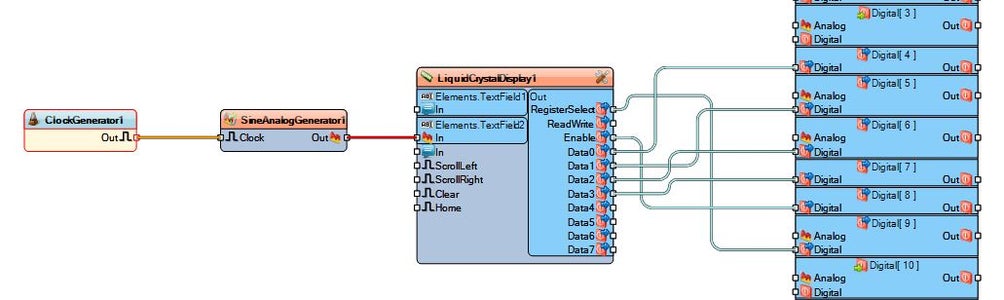
Now for my LCD Shield the connections will be different then a bare LCD sans the Shield, but this shields connections look like this. Picture 1
Now you can save the Visuino sketch and connect up you Arduino and Shield, then power it all on to upload it.
Picture 2 is another shot of mine when I loaded this sketch.
Picture 3 shows the entire layout, in Visuino
Let me know in the Comments how yours went.


