

Introduction: LED BLINKING USING ARDUINO NANO


Light-emitting diode (LED) is a two-lead semiconductor light source device used for indicating the output status by making it ON or OFF.
An LED is nothing but a p–n junction diode, which emits light when provided with power supply. When voltage is applied to the leads of an LED, it forces the electrons to recombine with electron holes within the device, emitting energy in the form of photons. This effect of emitting energy in form of photons is called electroluminescent. The color of the light is determined by the energy band gap of the semiconductor corresponding to the energy of the photon.
Using Arduino, Light emitting diodes (LED's) are handy. For that, connect a wire to digital pin 13 on the Arduino board, GND wire and VIN pin a voltage of 5v-9v. We get a constant or blinking LED flushing as we need.
Things we will need:
1) Arduino Nano A breadboard
2) A LED ( I used 3V at 20mA led)
3) A resistor 330 ohm
Step 1: About Arduino Nano Board
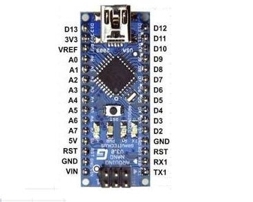
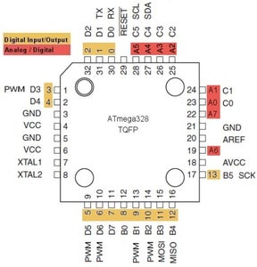
The Arduino Nano is a microcontroller(Atmel ATmega328) is an easy to use yet powerful single board computer that has gained considerable traction in the hobby and professional market. The Arduino is open-source, which means hardware is reasonably priced and development software is free. This guide is for students anywhere who are confronting the Arduino for the first time.
The Arduino project was started in Italy to develop low cost hardware for interaction design. An overview is on the Wikipedia entry for Arduino. The Arduino hardware comes in several flavors. This mini project covers the Arduino Nano board, a good choice for students and educators. With the Arduino board, we can write programs and create interface circuits to read switches and other sensors, and to control motors and lights with very little efforts.
Genarally, Arduino Board Inludes:
Programmer, Voltage Regulators Seral to USB Converter
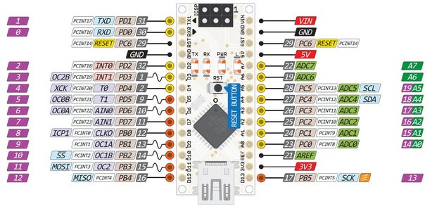
The Arduino-Nano board features an Atmel ATmega328 microcontroller operating at 5 V with 2 Kb of RAM, 32 Kb of flash memory for storing programs and 1 Kb of EEPROM for storing parameters. The clock speed is 16 MHz, which translates to about executing about 300,000 lines of C source code per second. The board has 14 digital I/O pins and 6 analog input pins. There is a USB connector for talking to the host computer and a DC power jack for connecting an external 6-12V power source, for example a 9 V battery, when running a program while not connected to the host computer.
The Arduino programming language is a simplified version of C/C++. If you know C, programming the Arduino will be familiar. If you do not know C, no need to worry as only a few commands are needed to perform useful functions.
The key features are:
Arduino boards are able to read analog or digital input signals from different sensors and turn it into an output such as activating a motor, turning LED on/off, connect to the cloud and many other actions.
You can control your board functions by sending a set of instructions to the microcontroller on the board via Arduino IDE (referred to as uploading software).
Unlike most previous programmable circuit boards, Arduino does not need an extra piece of hardware (called a programmer) in order to load a new code onto the board. You can simply use a USB cable.
Additionally, the Arduino IDE uses a simplified version of C++, making it easier to learn to program.
Finally, Arduino provides a standard form factor that breaks the functions of the micro-controller into a more accessible package.
Step 2: Connection Details & Coding
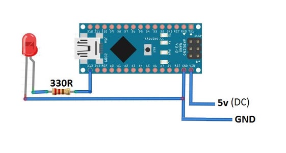
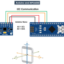
To connect LED's positive end to the one end of resistor and other end to Nano's digital pin 13 & negative end to Nano's ground.
To power Nano board, you can use USB cable or you can also connect a external power supply(5v-12v) by connecting positive pin to VIN and and negative to the ground.
CODE:
Inside Sketch_file
int led_pin=13;
void setup()
{
pinMode(led_pin,OUTPUT);
digitalWrite(led_pin,HIGH);
delay(1000);
digitalWrite(led_pin,LOW);
}
void loop()
{
}
Output:- Led will blink once...
But modifying code,
int led_pin=13;
void setup() {
pinMode(led_pin,OUTPUT);
}
void loop()
{
digitalWrite(led_pin,HIGH);
delay(500);
digitalWrite(led_pin,LOW);
delay(500);
}
Output:- Led will blink for infinity.
Conclusion:
The pinMode command sets the LED pin to be an output. The first digitalWrite command says to
set pin 13 of the Arduino to HIGH, or +5 volts. This sends current from the pin, through the resistor, through the LED (which lights it) and to ground. The delay(500) command waits for 500 msec. The second digitalWrite command sets pin 13 to LOW or 0 V stopping the current thereby turning the LED off. Code within the brackets defining the loop() function is repeated forever, which is why the LED blinks.


