

Introduction: LED Binary Clock


A Binary Clock!
I was recently looking at some binary clocks and I felt like Why not? I have everything to make one and I don't have a clock in my room.
So I decided to build one and here it is. Hope you Like it and maybe build your own.
It's a cool project because it's your very own, unique clock, it's easy to make, it's highly customizable in both size/shape and firmware/functions, it is Arduino based/compatible AND it looks good.
Step 1: What You'll Need

Materials/components;
- cardbord/wood box(you choose the size)
- DC WallWart 5V out at least 250 mA
- Arduino or Atmega328/168/88/48
- (if not using an Arduino) 16Mhz crystal and caps (the more precise, the better).
- 13x 220 Ohms Resistors.
- 13x LEDs (your preferred color)
- A lot of Wire.
- 3x pushbuttons (PCB mount)
- (optional) 1x LDR (light dependant Resistor) OR 1x Pushbutton (enclosure mount)
Tools;
- Soldering Iron and solder.
- Cutter/Xacto Knife.
- wire strippers.
- Computer (I guess you have one if you're reading this).
- (if not using an Arduino) USBtiny ISP.
Step 2: Selecting Your Box

The easiest and simplest enclosure is a cardboard box, you could also use a nicer plastic or wooden box, it's up to you.
Select your box, remove the back part from it.
if it's a cardboard box, you might want to disassemble it and reassemble it inside out, like I did, that way its easier to paint or, leave it like that and it looks great!
Step 3: Mark Your Box.
You need a 4x4 grid, but don't make holes just yet, as you won't fill it all the way.
in a cardboard box, I four it's easier to just make some small holes for the LED legs and insert them from the outside, other ways the cardboard will look awful and your LEDs won't be "snapped to grid".
At first, I marked my box on the inside, but later on I decided that I actuallly liked those Grid lines, so I did them on the outside too.
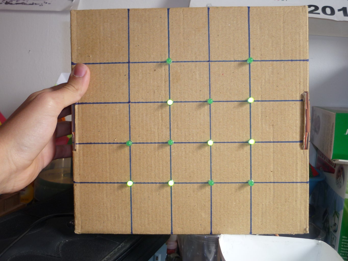
Step 4: Add Your LEDs


Place your 13 LEDs in your 4x4 grid as shown in the image above.
from the inside, Bend all the Leads and place a drop of hot melt glue on top of each (Bottom, actually) (see image 2).
Step 5: Wiring 1

connect together all the POSITIVE leads (the longer ones) from each LED.
Step 6: Wiring 2

Add one wire to each LED's NEGATIVE lead. instead of the positive lead, connect the NEGATIVE ones, contrary to the diagram above. Remember, all the POSITIVE ones are connected together, contrary to what the diagram shows.
Step 7: (If Using an Arduino)
- the 14 pushbutton will change minutes, adding one for each time you press it.
- the 19 pushbutton will change hours, adding one for each time you press it.
- the 18 pushbutton (optional) will turn ON/OFF the LEDs, but keep counting the time, this is useful for sleeping time. :)
- the 18 LDR (optional, instead of the pushbutton) will turn the LEDs when ther's no light, e.g. at night. but keep them on when there is, like in the day or at night, when you turn on the lights.
the proper LED to Arduino pin diagram is shown below, remember that it´s the other way around, instead of all to Gnd, all to 5V, etc.
Step 8: (If Not Using an Arduino) Assemble the PCB


I added the 2 time setting pushbuttons on the PCB, all the 13 resistors and the reset pushbutton.
place your crystal, remember, the frequency is not critical, as long as you specify it on the arduino software, if you don't know how to do this, stick with 16Mhz, also, if you´re using another frequency, remember that its recommended that it's a multiple of 8, e.g. 16mhz or 8 Mhz because Atmega chips are 8Bit micros.
if you're a beginner, it's recommended to use an arduino, or at least an arduino ready, pre-bootloaded chip.
the advantages of using an Atmega48 instead of an atmega328/arduino is mainly the price;
an arduino costs about USD $30, an arduino pre boot loaded chip costs about USD $6, and an Atmega48 costs only about USD $1.5.
NOTE: to be able to program Atmega chips without boot loader, using ISP from the arduino IDE you need to make some modifications to the IDE (I will not cover that in this guide).
if you use an Atmega48/88 without bootloader, you need to have some basic knowedlage on AVR fuses and how to work with the bare chip and program thru ISP.
remember to add a 2 pin header for power and, mark which pin is Gnd and which one is 5V and add a 3 pin female header for connecting the (optional) pushbutton or LDR. one pin to Gnd, one to 5V and the other one to digital pin 18 (analog 4).
Step 9: Test Your Clock.
Download the firmware below, there are 2 files, one for 24 hour mode and one for 12 hour mode.
At this point it should be (almost) fully assembled, but already fully working, so flash your micro controller and try adding some minutes/hours and check if it changes every minute. also check that the numbers it displays are correct, if not, check all your connections, check that the program you uploaded is the correct one and check for power good (green LED on Adruinos).
if you don't manage to solve your problem, post a coment describing it or email me at emihackr97@gmail.com and I will try and help you.
the video shows the programming and testing process.
Attachments

Step 10: Glue Your Pcb/arduino in Place
at this point, your clock should be allready tested and working, because, after this step, you won't be able to make any soldering or other kind of rework.
Step 11: Power Supply.


for the power supply I used an old WallWart I had lying around that outputs 5 volts regulated DC, I also made a power extension (for the 5v side) because the wallWart's wire wasn't long enough.
To be able to plug it in, you just need to cut the tip and exchange it for a 2 pin female header (in case of using your own pcb) or a male header (in case of using an arduino).
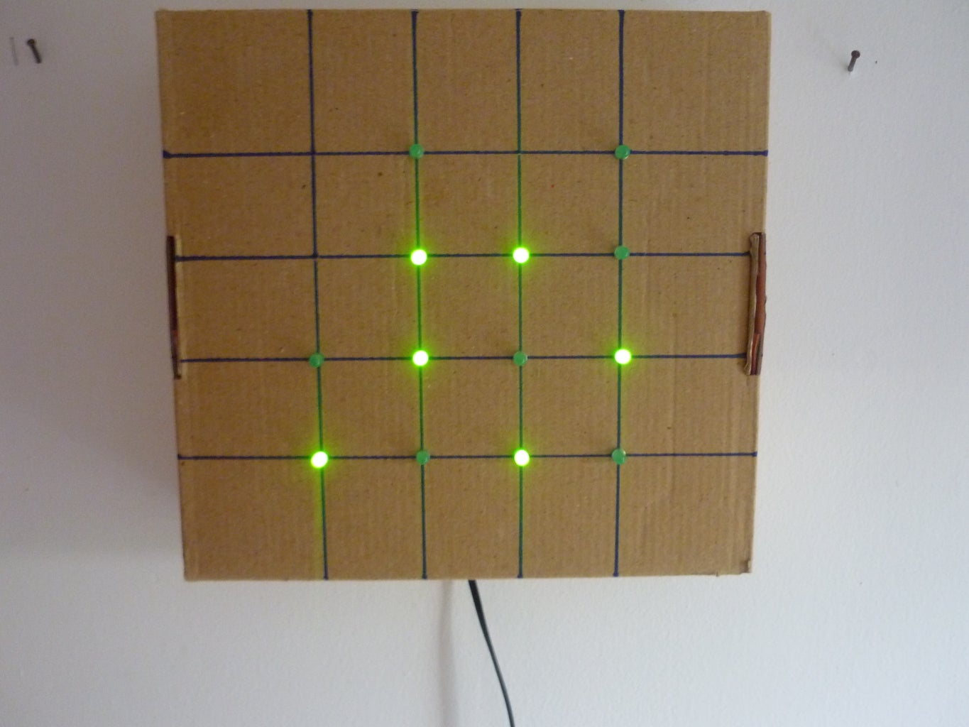
Step 12: How to Read It

the secret lays in understanding how it works, it's really simple!
It is a binary clock, it's a bit harder to read but that makes it cooler, you'll get used to it.
the first 2 colums correspond to hours, toe 3rd and the 4th correspond to minutes. the 2nd and 4th colums are units and the 1st and 3rd ones are 10 of the corresponding units (hours, Minutes).
you need to add the lit up LEDs to get the time, see image 2 for an example (it's not as hard as it might seem, it's actually really easy)
remember , if you make the 24 hour version, you will have a 12:00+ hour in the afternoons, with the 12 hour one, you will have the normal time. (i think everybody understands this part).
It'l get really easy after a week or two of reading your new super, unique cool clock.
Step 13: Finally, Place It!


Finally, place it on the wall and enjoy!
remember to set the correct time.
also remember that, if the power goes out, the current time will be lost.
Step 14: Future Additions!
- add an RTC (Real Time Clock) so it doesn't loos the time every time it is unplugged.
- add a day of the week function.
- add an alarm function that has day-dependant alarms and multiple ones.
- something else I will think of.

Runner Up in the
Clocks Challenge

Participated in the
4th Epilog Challenge

Participated in the
Make It Stick Contest 2


