

Introduction: LED Chase Effect Using an Arduino
Turn your Arduino into KITT from Knight Rider! This tutorial is on how to program and assemble an LED chase effect Arduino project. This is a beginner project and can be used as a stepping stone for more complicated projects down the line.
Materials:
- A computer with the Arduino IDE (Integrated Development Environment, a fancy way of saying an application that can process code) installed. You can install the IDE at the Arduino website.
- An Arduino board from any kit
- A breadboard
- 21 wires. They can be any color, but one (and only one) must be black. I find it easiest to have 1 black, 10 of one color, and 10 of a different color
- 10 220 ohm resistors
- 10 LEDs
- 1 USB-A to USB-B cord
Note: The Arduino IDE uses the Java programming language. We will be using the conventions and syntax of Java throughout this tutorial.
Step 1: Start With Your Code

Open up your Arduino IDE. You can go ahead and delete any text already written in as we will be creating our own. As good practice, put your name and the date at the top of the script and comment them out by preceding it with //.
Step 2: Create Variables

To make things easier on ourselves later on in the program, it will be best if we create variables for numbers or items we will be referring to a lot throughout the program. Let's break down the different lines:
- byte ledPin[] = {4, 5, 6, 7, 8, 9, 10, 11, 12, 13}; : This is creating an array (think of a list with a set number of items in it) of where our LEDs will be placed on the board. When we start assembling the physical portion of this project, the LEDs will correspond to one of the spots on the board with the same number.
- int ledDelay(65); : This will cause a delay of 65 milliseconds.
- int direction = 1; : This is how we will change which direction our lights will move in.
- int currentLED; : We are creating a variable that is currently empty. We will assign it a value later in the program.
- unsigned long changeTime; : This is another variable that we are currently leaving empty. The reason it has a different type (unsigned long vs. int) is because of a function we will be using it with later in the program. If we changed this type to an int, our program would not run.
Step 3: Create Your Starting Setup

We will now use a function that will only run once at the very beginning of our code. This is called the setup. Again, let's break this down line by line.
- void setup() { : This is calling the function setup (which is a function that is already known by the Arduino IDE) and running it once.
- for (int x = 0; x < 10; x++) { : This is a for loop. We first initialize an integer x and set it to 0, then tell it to run as long as x is less than 10, and finally tell it for each iteration through the loop to add one to x.
- pinMode(ledPin[x], OUTPUT); : This is telling the Arduino to make sure that the pin that is currently selected (remember that x stands for a number, so for the first iteration it will take the LED that is in the first position) and set it so it can display light.
- } : This is closing the for loop.
- changeTime = millis(); : This sets the variable changeTime to the value of the function millis(). millis() is a built-in function that returns how long it has been since the program started running. millis() returns the type unsigned long, which is why we had to make changeTime into an unsigned long type. If we attempted to compare two different types, like an unsigned long and an integer, our program would break.
- } : This closes the setup loop.
Step 4: Create a Function to Switch the LED

Up until this point, we have been using built-in functions. Now, it's time to build our own so we can switch our LEDs on and off as well as move the light back and forth. Let's break it down:
- void changeLED() { : This is the start of our function that we will call changeLED().
- for (int x = 0; x < 10; x++) { : This is the exact same for loop setup that we wrote earlier. We are taking an integer x and setting it to 0 and running the loop, adding one each time until we reach 10.
- digitalWrite(ledPin[x], LOW); : This step is kind of funky. The function digitalWrite is how we control the output of the LEDs. In this case, it will take the LED in the position of x and set it to LOW, which really means it is turning it off.
- } : This closes the for loop.
- digitalWrite(ledPin[currentLED, HIGH); : This will take the LED in the position of currentLED (remember that currentLED really stands for a number as we initialized it in the beginning) and set it to HIGH, which means it will display light.
- currentLED += direction; : This line could also be written as currentLED = currentLED + direction;. It takes the number stored in currentLED and adds the value of direction to it. This is a significant step, as this is what allows our light to move from one LED to the next.
- if (currentLED == 9) { : This is a conditional loop. It will compare the value of currentLED against 9, and if they are equivalent (==), then it will run the following code. If it is not, it will skip this for loop entirely.
- direction = -1; When the light reaches the rightmost LED, this code is telling it to set the value of direction to -1. When the changeLED() loop runs again, it will force the light of the LED to travel left.
- } : This closes the for loop.
- if (currentLED == 0) { : This is another conditional loop, but this time it will only run if the value of currentLED is equivalent to 0.
- direction = 1; : This is similar to the previous for loop, but this time it will set direction equal to 1. When changeLED() is run again, the light will start moving to the right.
- } : This closes the for loop.
- } : This closes the changeLED() function.
Step 5: Creating the Loop That Will Constantly Run

We're almost done with the coding portion of this project! All that's left is to add the function that will put everything together. So far, we have set up our LEDs and written a function to make the light move, but we have never called it so that it can be run. We will do that in the loop function. Here's the loop function broken down:
- void loop() { : This is starting the function called loop. loop() is a built-in function and therefore is pre-programmed to run automatically.
- if ((millis() - changeTime) > ledDelay) { : This check to see if it has been at least the value of ledDelay (in our case 65) milliseconds since the last change of LEDs. If it does, it will proceed with the following code.
- changeLED(); : Here we are calling our changeLED() function, which means we are asking it to run in it's entirety.
- changeTime = millis(); : This overwrites the value of changeTime to be the current value of millis(). This helps ensure that the program always waits ledDelay milliseconds before switching the light to the next LED.
- } : This closes the for loop.
- } : This closes the loop() function.
Congratulations! We have finished with the coding portion. In order to make sure there are no mistakes, click the Verify button (the checkmark) in the upper left corner. If you come across an error, make sure you have no spelling errors and that every line ends with {, }, or ;.
Step 6: The Physical Portion

Now that all of the programming is out of the way, it is time to grab the breadboard and start adding our hardware. The above diagram shows exactly how everything should be set up. The color of the wires does not matter except for the black one. In electrical fields, black wires denotes the ground, which is a very important thing to have when working with circuits and, in our case, an Arduino.
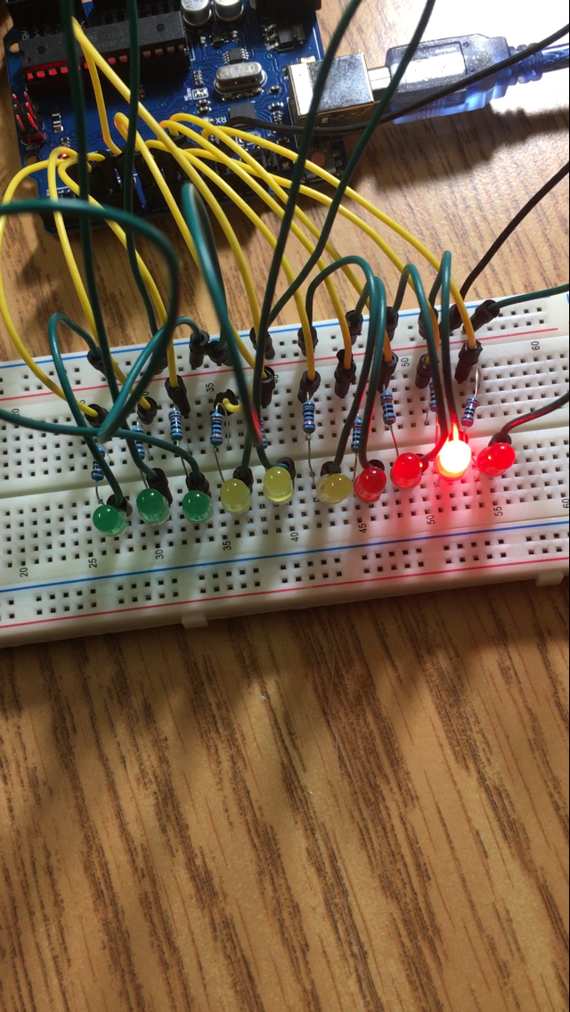
Step 7: The Final Product
Once you have everything set up, take your USB-A to USB-B cord and connect your Arduino board to your computer. You can then press the Upload button (a right facing arrow) in the upper right corner. Once it finishes, uploading, it should immediately start running the code and your light should be racing from one side of your LEDs to the other. Congratulations!
If you are having issues, here are a few common troubleshooting tips once the code has been verified:
- Check to make sure you are using the COM3 port. To do this, go to Tools in the upper navigation bar, click Port, and then select COM3 and re-upload your code.
- Make sure all of your connections are solid. Sometimes items do not always sit correctly in the breadboard, so gently push everything into the breadboard.
- If one LED is not displaying while the others are, try replacing the items pertinent to that LED one at a time. First try replacing the LED, then try replacing the resistor, and so on.


