

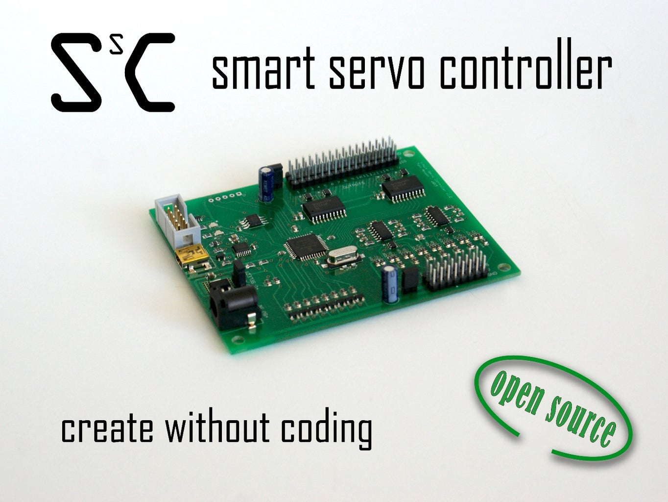
Introduction: LED PWM With Smart Servo Controller


In this demo I'm going to show you how to connect a color LED to the Smart Servo Controller.
The Smart Servo Controller can output high speed PWM signals that are suitable for driving LEDs. For high power LED's you must use transistors or mosfets.
For more information on the Smart Servo Controller checkout our kickstarter page here: https://www.kickstarter.com/projects/143152889/smart-servo-controller
Follow us on facebook here: https://www.facebook.com/smartservocontroller
Step 1: Connect the LED to the MOSFETs


The first step is to connect the LEDs to the MOSFET. By doing this you can drive the LEDs with a higher voltage and current then the Smart Servo Controller can provide.
Step 2: Connect the FETs to the Smart Servo Controller


Connect the MOSFET gates to the outputs on the SSC board. Connect the red LED to channel 1, green LED to channel 2 and blue LED to the channel 3 output.
The board is going to supply power to the LEDs. Connect the positive and negative rails from the servo output channel to the LED and FETs.
Step 3: Control Theory


Connect the IR distance sensor to the channel 1 input on the SSC board.
We want the LEDs to do the following:
- When far away slowly blink red.
- When closer blink faster yellow.
- When even closer turn a steady green.
- When extremely close to the sensor we want it to ramp up to blue.
To do this we are going to use the sequence rule and have the blinking / ramp of the LED outputs a sequence animation.
Step 4: IO Setup

First we set the input to analog for the IR sensor.
We set the outputs 1-3 to be HS PWM. Notice that the default amount will now be in %.
HS PWM runs at about 15kHz. The regular PWM runs much slower at about 600-2000Hz. Filtering might be required if using the regular PWM output types. There are only 5 High Speed PWM outputs.
Step 5: Red Blink


We create the first rule for blinking the red LED slowly.
Select a sequence output and set it to channel one. Using the graph editor add points and arrange them into a square wave. Pressing I changes the mouse to insert mode, M changes it to move mode and R is remove mode.
The options for the sequence are as follows:
- Linear Interpolation - the controller will interpolate between the data points to create a smooth transition.
- Interruptable - the animation will stop if the input conditions go false.
- Restartable - if the input conditions go false then true and the video is playing, the video will restart.
- Stop at End - this will only let the animation play once even if the input conditions are still true.
The Trigger on End and Trigger on Interruption allows the animation to signal other animations to start playing.
We add input conditions so that this rule is active when the distance sensor is detecting far objects.
Step 6: Yellow Blink


This rule is similar to the last one with the exception that the blink rate is faster. The graph shows this by being shorter time duration. To make yellow we turn on the red and green outputs at the same time. That is why there are two graphs.
Set the conditions so that this animation will turn on when the previous sequence has turned off.
Step 7: Green Solid


Since we are having a solid color for this distance range, just use the output state rule.
Se the input conditions in a similar manor as before.
Step 8: Blue Ramp Up


For this section we want the blue LED to ramp up. Adjust the graph to be a ramp.
Set the input condition so that this rule is active for the close distance ranges.
Thanks for reading. Don't forget to support our kickstarter and like our facebook page.


