

Introduction: LED Sequence for Arduino: Star Trek Tricorder


Welcome to my first Instructable for my first Arduino project!
The goal of this project is to re-create the LED chase from a Star Trek Tricorder Mark VII Medical Scanner as shown in the video clip.
Step 1: Materials

-Arduino Uno w/USB cable
-Solderless Breadboard
-3mm Green LEDs, 3.2-3.4V, 20mA forward current (need 10)
-100 ohm resistors (need 10)
- Breadboard jumper wires (need 11)
*NOTE: Picture shows 5 yellow LEDs and 5 green. This was an earlier version of the project. The final version had 10 green.
Step 2: Breadboard Connections: LEDs

For this project, we'll use a solderless breadboard for ease of assembly. We'll start with the LEDs.
-Starting in whichever column of the breadboard you prefer (I started around column 5 just to give myself some space), connect the anode (longer pin) of each LED in the sequence to Row J on the breadboard. This is the bottom row before the power rail.
-Connect the cathode (shorter pin) to the "-" row of the power rail. You'll have to bend the pins apart slightly to get them both in.
-Connect the rest of the LEDs in a row this same fashion, leaving a little space in between each if you prefer. Because the anode of each LED is in a separate column of the breadboard, it will receive it's own power from a specific pin on the Arduino, allowing individual control. All of the cathodes are connected to the "-" row of the power rail so that they can share a common ground connection back to the Arduino.
Step 3: Breadboard Connections: Resistors

Each LED in the sequence will need a resistor so it doesn't pull too much current and fail catastrophically.
-Calculate the type of resistor needed using Ohm's Law: R=V/I
-In this case, "V" (voltage) is the supply voltage (5V from the Arduino) minus the voltage of the LED (3.2-3.4V)
-"I" is the forward current that the LED can handle, in this case 20mA or .02A.
-So the math looks like this: R =(5V-3.2V)/.02A --> R=1.8V/.02A --> R= 90Ω
-The closest adequate resistor I have is 100Ω so I used that. It's color code is Brown-Black-Black-Black-Brown
-Connect one end of each resistor inline (in the same column) with it's LED, right next to the anode connection (row "H" or "I" will work well).
-Connect the other end of the resistor to the same column, but across the break. You'll need to leave room at the head of each column for the jumper wire to the Arduino pin, so leave row "A" open. Rows "B" and "C" are good for the end of the resistor (see pic)
Step 4: Breadboard Connections: Jumpers

-Use row "A" for one end of each jumper wire that will connect to the Arduino. Make sure each jumper wire is connected to the same column as its corresponding resistor and LED. There should be 10 of these jumpers.
-The 11th jumper connects the cathodes of each LED back to ground on the Arduino. Place one end of this jumper in the "-" row, making sure it is not past the break in the breadboard.
Step 5: Arduino Connections

We will use pins 3-7 and 9-13 on the Arduino to output voltage to the individual LEDs. For the return, I used the ground pin on the Arduino that is just past pin 13. We are not using pins 0-1 because they are involved in serial communication and I am a novice at this and don't fully understand how the conflicts might become a problem, so I just avoided them. Otherwise, the spacing of the connections is fairly arbitrary other than being neatly aligned. You could start by plugging the jumper wires into the Arduino or into row A of the breadboard. I left some small gaps in the breadboard just so the cables weren't too cramped.
*You don't need to plug the USB cable from the Arduino to your computer until you're ready to test your programming, so put that cable on standby.
Step 6: Programming: 1) Name the Pins

The first step of the code for this project names the Arduino pins based on their corresponding LEDs. This is not necessary, but makes the rest of the coding process easier.
Step 7: Programming: 2) Setup

-Set up each pin as a digital output
Step 8: Programming: 3) Create the Looped Sequence

-Each "digitalWrite" command tells the Arduino to either deliver ("HIGH") or stop delivering ("LOW") voltage to the pin specified.
-Each "delay" command tells the Arduino how long to wait, in milliseconds, before proceeding to the next line of code.
-Lines beginning with "//" are explanatory and do not effect the sequence
Step 9: Uploading the Sketch to the Arduino
Once the code is finished:
-Click the check button in the upper left hand of the Arduino IDE to verify the code. You will either get an error message if something is wrong, or a "done compiling" message if all is well.
-Connect the Arduino to your computer using a USB cable.
-Click the forward arrow at the upper left hand corner of the Arduino IDE to upload the code to the Arduino. Once you've done this, your sequence should begin to loop!
Step 10: Enjoy the Fruits of Your Labor
-Now you just have to build a smaller version and encase it in a Tricorder. Then find an Instructable for a spaceship, and you're all set :)
Step 11: The Code Itself
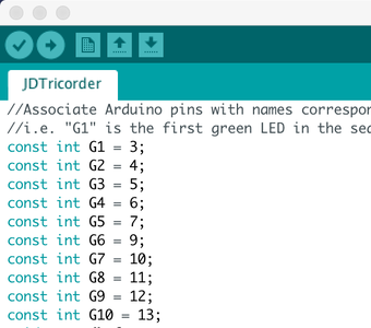
//Associate Arduino pins with names corresponding to the type and order of LED.
//i.e. "G1" is the first green LED in the sequence.
const int G1 = 3;
const int G2 = 4;
const int G3 = 5;
const int G4 = 6;
const int G5 = 7;
const int G6 = 9;
const int G7 = 10;
const int G8 = 11;
const int G9 = 12;
const int G10 = 13;


void setup() {
  // set all pins to output mode
  pinMode(G1, OUTPUT);
  pinMode(G2, OUTPUT);
  pinMode(G3, OUTPUT);
  pinMode(G4, OUTPUT);
  pinMode(G5, OUTPUT);
  pinMode(G6, OUTPUT);
  pinMode(G7, OUTPUT);
  pinMode(G8, OUTPUT);
  pinMode(G9, OUTPUT);
  pinMode(G10, OUTPUT);
}


void loop() {
  // scrolling chase effect to match Star Trek Tricorder Mark VII Medical Scanner
  digitalWrite(G2, HIGH);
  digitalWrite(G9, HIGH);
  digitalWrite(G1, LOW);
  digitalWrite(G8, LOW);
  delay(35);
  digitalWrite(G3, HIGH);
  digitalWrite(G10, HIGH);
  digitalWrite(G2, LOW);
  digitalWrite(G9, LOW);
  delay(35);
  digitalWrite(G4, HIGH);
  digitalWrite(G3, LOW);
  digitalWrite(G10, LOW);
  delay(35);
  digitalWrite(G5, HIGH);
  digitalWrite(G4, LOW);
  delay(35);
  digitalWrite(G6, HIGH);
  digitalWrite(G5, LOW);
  //this next delay near the center of the sequence is longer to imitate the heartbeat effect of the scanner
  delay(82);
  digitalWrite(G7, HIGH);
  digitalWrite(G5, LOW);
  digitalWrite(G6, LOW);
  delay(35);
  digitalWrite(G8, HIGH);
  digitalWrite(G1, HIGH);
  digitalWrite(G7, LOW);
  delay(35);
}

Participated in the
First Time Author Contest 2018


