

Introduction: LED VU-Meter With Arduino UNO


A volume unit (VU) meter or standard volume indicator (SVI) is a device displaying a representation of the signal level in audio equipment. In this project I have used LEDs to indicate how much intense the audio signal is.When the audio intensity is very high then all the LEDs glow but when the intensity is too low then only middle two leds glow.
Step 1: EQUIPMENTS REQUIRED


1. Arduino UNO/Mega/Nano/Mini. (1 pc)
2. Colorful LED s. (8 pc)
3. Jumper wire.
4 .Male ports/poles.
5. Vero board. (1 pc)
6. Mic. (1 pc) . Wire must be soldered to the poles of the mic for connection.
7. Resistor - 10K (3 pc)
8. Capacitor - 0.1uF (1 pc)
9. Soldering kit.
10. 12/9 V DC Source.
Step 2: CIRCUIT DIAGRAM


Circuit diagram is very simple.
1...2...3..4.. no. are written below the LEDs (in the fig.). LED no.1 is connected the Digital pin 3 of arduino uno. Similarly LED no.2 is connected the Digital pin 4 of arduino uno. So the list of LED pin no. and its connection to the digital pin is given below:
LED no.1 --> Digital pin 3 of Arduino UNO.
LED no.2 --> Digital pin 4 of Arduino UNO.
LED no.3 --> Digital pin 5 of Arduino UNO.
LED no.4 --> Digital pin 6 of Arduino UNO.
LED no.5 --> Digital pin 7 of Arduino UNO.
LED no.6 --> Digital pin 8 of Arduino UNO.
LED no.7 --> Digital pin 9 of Arduino UNO.
LED no.8 --> Digital pin 10 of Arduino UNO.
The condensor mic is connected to Analog pin A0 via a RC circuit.
There must be a common GROUND connection between the Arduino UNO and the LEDs.
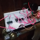
Step 3: SOLDERING THE LEDs


The soldering must be neat and clean .
Step 4: WORKING PRINCIPLE


The condenser mic is used to receive the audio signals. The audio signals (in form of sound energy) gets converted to electric energy with the help of the RC circuit. Then that is fed into the Analog pin of Arduino UNO. So if we can print that values in the serial monitor of Arduino UNO, then we will be seeing different values from 0 to 100 or more depending upon the volume of the audio device used. When the value is 0 it means that the there is no input signal. So more louder the sound , higher the value of the analog input. In the code I have divided the analog input value with 10. This is not mandatory , the same thing will happen if we don't divide with 10. So anyone can comment the line in the arduino code and proceed.
So when the analog input value is less the only LED no. 1 and 2 will glow/blink. As the analog value increases the corresponding LEDs will start glowing/blinking. When the analog value reaches its maximum level than all the LED will glow/blink.
You can clearly understand the concept of LED VU Meter if you see my youtube video on LED VU Meter with arduino UNO (video already provided at last).
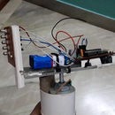
Step 5: FINAL SETUP


The set-up is ready now. We will use our mobile phones to play the music and hold the speaker of our phone near the mic of LED VU Meter.
Step 6: ARDUINO CODE
You must have the Arduino IDE installed in your PC or laptop.
Attachments

Step 7: VIDEO
Like | Share | Comment on this video.
Don't forget to subscribe to my channel
#DChaurangi


