

Introduction: LM1117 Linear Voltage Regulator


The LM1117 is a popular linear voltage regulator that can provide steady voltage to your Arduino and ATMega projects. This unit comes in fixed output voltages of 1.8, 2.5, 3.3, and 5 volts or can be bought as an adjustable unit, able to output 1.25 to 13.8 volts. This unit works with an input voltage of up to 20 volts, can handle up to 800ma of current and some versions work down to -40 degrees celsius, making it ideal for outdoor use or high altitude balloon flights. This unit also comes with current limiting and thermal protection. The LM1117 is made by Texas Instruments. You can find the data sheet here: Data sheet
I use this unit to provide clean 5 volts and 3.3 volts for my ATMega projects typically dropping the voltage of a 9 volt battery or 12 volt wall power supply. The LM1117 has a drop out voltage of 1.2 volts at 800ma meaning you must provide 1.2 more volts than you are outputting.
Overall, the LM1117 is a super easy to use, high quality voltage regulator that should be found in every electrical engineer and hobbyists tool box. The LM1117 is RoHS compliant.
Step 1: Buying Options


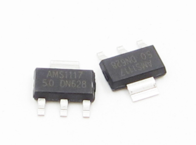

The LM1117 comes in many different forms. Personally, I have only used the DCY package but it also comes in KTT, NDE, NDP, and NGN form. I would recommend the NDE package for breadboard testing or in a circuit using through hole pieces. The NGN package is good for a complex circuit that requires many power rails. The WSON package has the smallest footprint at 4 mm by 4 mm while the DCY package I use has the smallest width at 6.5 mm by 3.5 mm.
The LM1117 base model has a temperature range of 0-125 degrees celsius. While this is adequate for most projects, the LM1117I units work down to -40 degrees celsius. I typically purchase this unit from Arrow.com. Each LM1117 costs around $0.90 - $1 depending on package and type. If you're buying in bulk, the price drops even cheaper. Buying 100 of these drops the price per unit by about 25%.
Sparkfun also sells the adjustable unit here: Adjustable LM1117 - Sparkfun
Step 2: Hooking It Up - LM1117 Fixed Voltage


Dependent on whether you are using an adjustable or fixed unit and your application, hookup will vary. The fixed unit is very simple to set up. Along with the unit, one to three capacitors are needed. The data sheet specifies 10uf tantalum capacitors but I've found that polarized aluminum capacitors work just as well.
To set up, attach one capacitor from the output pin of the LM1117 to the ground pin of the LM1117. Next, do the same going from the input pin to the ground pin. These capacitors are polarized. Ensure the positive leg of the capacitor is in the input/output and the negative leg is connected to ground. Reversing the polarity of either a tantalum or aluminum capacitor will make it spark and catch fire. I experienced this first hand, the smell of burning capacitor is not a pleasant one.
Now plug a wire into the output terminal, this will connect to your power source. Two wires should be connected to the ground terminal of the LM1117, one for the input voltage and one for the output. Connect one of these wires to the negative wire of your power source. The input wire and not connected ground wire should now be hooked up to your multimeter. Turn on your power supply and check the voltage reading of your power supply. You should now see your desired voltage!
I always use at least two capacitors with the LM1117, however the data sheet does specify that if the power supply is close, only one capacitor from the input line to ground is needed.
Going further, a 0.1uf capacitor can be added between the input and ground lines to reduce noise. A 1N4001 diode can also be added between the output and input legs to protect against reverse voltage.
Troubleshooting
I have power plugged in but there is no output voltage:
Check your wiring connections and that all electrical connections are good. I spent a week trying to get this thing to work because I kept getting readings of 0 volts or a dropping output voltage. It turned out, my unit wasn't making connection with the metal inside the breadboard so I wasn't completing the circuit. I know, I'm a dummy. The dropping voltage I saw was the discharging capacitors.
I have power plugged in but there is no output voltage, all of my connections are correct and making electrical contact:
The LM1117 can have a voltage dropout of as much as 1.2 volts. This means you must provide at least 1.2 more volts than you plan to output. Try a higher voltage power source.
Step 3: Hooking It Up - LM1117 Adjustable Voltage
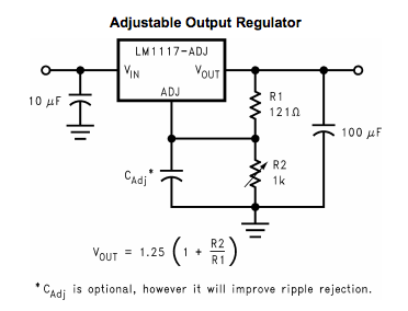
The adjustable unit is valuable if you need a less common voltage or are doing tests with many different voltages and don't want to buy a fixed unit for each voltage. The adjustable regulator works with a similar circuit as the fixed unit. In addition to the capacitors, the adjustable LM1117 uses two resistors to set the output voltage.
It is important to note that the adjustable unit uses one 10uf capacitor and one 100uf capacitor. To set the voltage, two resistors are used. These resistors, R1 and R2, must have special values to achieve the voltage you wish. To determine the resistors needed or the voltage produced by a set of resistors, you can use this Voltage and Resistor Calculator. This calculator is meant for the LM317 but works with the LM1117 but, the circuit diagram on the page should be ignored.
To find the voltage produced by two resistors by hand, use the formula -- V out = 1.25(1+R2/R1). Note that the value of resistor 2 must be more than the value of resistor 1. The value of resistor 1 should be between 1 and 1000 Ohms.
For example, to produce 5 volts, you could use a 1000 Ohm and a 3000 Ohm resistor. Likewise a 100 Ohm and 300 Ohm resistor would work just as well.
Step 4: Testing

If all works out, you are now able to provide steady power for your projects. The ATMega microcontroller, the brains of the Arduino, can be used alone. Check out an Instructable on how to do that here: Standalone Arduino. The ATMega requires stable power of up to 5.5 volts, any more and the thing could become unusable. That is why a voltage regulator like this is so important. To prove this works, upload the blink sketch to your ATMega and provide 5 volt power from your LM1117. Success!
I would highly recommend a 0.1uf capacitor between the positive and negative rails when your power source or LM1117 is far away from what you are powering. The blink sketch in the video above would work inconsistently, once a capacitor was added, it always worked. Note that the power source was over a foot away from the ATMega, when in close proximity this isn't typically necessary.
Thank you for taking time to read this Instructable, I hope you have a better grasp of how to use the LM1117 linear voltage regulator!


