

Introduction: Laser Guided Truck


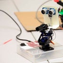

My college sponsors a competition that is really quite simple in concept. Instead of driving an RC car with the use of the RC chipset, drive the car using a 10kHz modulated laser. The constraints were simple. Use what ever comes in the box and up to $25 dollars worth of parts (plus incidentals). This can be done in several ways. I decided to do it in a purely "analog" fashion. No micro-controller, no brain or processor of any kind. All data manipulation through fairly basic gates and logic. That being said THIS IS NOT A PROJECT FOR BEGINNERS. With the help and guidance of several Professors, It still took me 100+ hours of work and troubleshooting. I would also like to mention that this is a starting point unless you use exactly the same car as I do. I would suggest that you choose any RC car you want, and use this as a guide.
Here are the rules as I followed:
http://www.et.byu.edu/~bmazzeo/LTR/2013/rules_2013.pdf
At the end of this step I have a pdf of my lab notebook, so I would suggest that you follow along for all the calculations worked out in detail.
THIS INSTRUCTABLE IS A WORK IN PROGRESS. The rest of the instructions should be up by this weekend. (March 3rd, 2013)

Step 1: Materials

Parts
- 4 Solar Cells
- Resistors:
- 4 10ohm
- 4 82ohm
- 4 1.4k ohm
- 4 1k ohm
- 4 47k ohm
- 4 560k ohm
- 8 10k ohm
- several breadboard mount variable resistors
- Capacitors:
- 4 0.01 uF
- 2 1 uF
- 2 10 uF
-Diodes:
- 4 1N4148
- 2 LF347 OpAmp Chips (TI has them)
- 1 9 Volt
- 1 9 Volt battery clip
- 1 L4S32F Quad OR Gate chip
- 4 LM317 Voltage Regulators (Variable)
- 1 78MO5CT Voltage Regulator (5V)
- Wire
- 2 breadboards
- electrical tape
- duct tape
Tools
- soldering Iron
- solder
- solder sucker
- drill
- dremel tool
- wire cutters
- wire strippers
- Oscilloscope
- Function generator
- DMM
- Power supply
- hot glue gun (and glue)
- scissors
(without the bolded tools listed, this project is almost impossible)
Step 2: RC Car Specs

Here are a couple of pictures of the car RC circuit. (Also found at this site http://www.et.byu.edu/~bmazzeo/LTR/2013/tech.phtml)
Note that if you do something wrong, that the H-Bridges could easily blow out. This is what happened to me because I didn't adequately protect from spikes.
One of the first things that you need to do is solder to the four necessary pins. I used an SMD solder station to do so. You must NOT cross any of the pins or melt the IC. If you do, you will have to build your own H-Bridge, which is a Pandora's Box of problems. So, be careful and do not solder to the board until you have checked and double checked the connections. When finished, use hot glue to secure the wires.
Also note that each board, even for the same model of truck is slightly different. You may have to do some looking around to find the right pins and chips. I would suggest soldering some leads off the negative and positive terminals at this point as well.
Step 3: High Pass Filter

Next we need to construct a high-pass filter.
The solar cells will be collecting in all light that hit them, and we only want the modulated laser to get through to our design. So we set the lower corner to be 10kHz +- 10%. In our case, three resistors and one capacitor will do the job.
In our case we can use 0.01uF as our capacitor and as our resistor the 1.5k ohm and 91 ohm in series.
Now for the first test.
Put a 10kHz test source on the capacitor and check with the oscilloscope that it indeed does pass. Then put a signal lower than that on the capacitor and check the output. It should be zero. If not, then you need to rebuild the high pass filter. The amplitude of the signal that you put in should be above 1V. Otherwise it will be hard to see on the o-scope. Our real signal is less that 0.036V.
Step 4: Amplification

Now for the amplification. I had to really play around with the gain. If you are unused to using op amps, look on Wikipedia here (http://en.wikipedia.org/wiki/Operational_amplifier) It will walk you around the basics.
For the first stage of amplification I did an inverting set up.
Feedback resistors: 560k ohm (consider using a 1k ohm variable resistor, so you can tune the gain)
R2: this is the high pass filter
Set up a test source and feed it in, through the high pass filter (make sure it is over 10kHz) with an amplitude of about 470mV. Make sure that it has a gain of about 10 V/V. (ie the output Vpp on the o-scope is about 4.7V)
For now, power the chip with a +-9.6 Volts. This will change later.
Step 5: Rectification

The next step it to rectify the signal, so that further amplification isn't in vain. The diode can be either forward or reversed biased, because the signal coming in is a sine wave. After this step, it is a half wave rectified wave. For further information on rectifiers refer to Wikipedia. ( http://en.wikipedia.org/wiki/Rectifier)
I used different values for R and C depending on the channel I was controlling. I used a 10uF on the Right and Left channels and 1uF on the forward and reverse channels. The reason is that the bigger the C value, the longer the signal is triggered to the RC chip. Fiddle with R and C values until the car holds the turns and the forward/reverse like you want after all is said and done.
To test the functionality of this step, first use the oscilloscope on the output side of this circuit. On the input side put a test signal of 1Vpp (an AC signal). The output should show a half wave rectified circuit.
Now that this works, have its input hook into the output of the previous two stages. With the oscilloscope in the same place as before, put a test source in on the filter of about 1Vpp. Make sure there is a rectified output. If so, then you are doing good.
Step 6: Second Gain Stage

This stage needs to be a non-inverting amplification. We want all our signals from now on to be positive. The diagram shows the resistor labeled Rx (I used 47k ohm). I think it would be best to use a variable resistor and be able to use it to fine tune our gain. As can be seen in the next step's picture, I did not do so in the first iteration. The unmarked resistor to ground on the (-) input of the op amp is a 1k ohm. I had to adjust this for each channel and that is why I suggest a variable resistor.
Step 7: Power the System (breadboard)


In the picture, you can see how I hooked up the breadboard. The red and black leads in the lower left of the picture run to the 9V battery clip. The yellow line on the right hand of the picture hooks the two inner rails together as a ground. The positive of the 9.6V batter hooks directly into top positive rail. The negative (really a ground) goes to our lower inner rail (the positive rail closest to column j )
When this is done, hot glue the battery clip in place. If it pulls out while the car battery is hooked it, it will burn out your chips and fry your resistors. You don't want this to happen.
Step 8: Further Information
For more on this project, check out my website which contains the entire build journal in pdf.
https://sites.google.com/site/engineeredbyluck/lasertruck


