

Introduction: Laser Magnetic Field Mapping


Have you ever wanted to visualize magnetic fields better?
Magnetic forces, invisible and acting at significant distance, fascinated me since a young age as an instance of "real magic".
You can get a good sense of the strength and direction of a strong magnetic field by loosely holding a magnet in your closed fist, but I wasn't happy with the resolution or clarity of this method: It's too hard to discern torques from translational forces, and if your hand confines the magnet's rotation, you can fool yourself about the direction of the field (For instance, if you rotate a magnet 180 degrees, you could change attraction to repulsion). Also, if one goal of such a visualization tool is to share the shape of the field with others, you want something visible, so a magnet held in your hand won't do.
I wanted something like a compass, but which could point in any direction in 3D space, not just directions within the compass's plane, or a horizontal plane. It should be well balanced, able to pivot with low friction around two perpendicular axes, and carry a strong enough magnet on it that it would overcome whatever friction the pivots had, to align itself with the field. A magnet that is free to orient itself, but is held centered in a given position, will turn until it's poles align with the local magnetic field lines. You can use something like this to visualize where the magnetic field flows around complex things like magnetic levitation apparatus.
Materials and Tools I used
- laser cutter. You can make a magnetic gimbal compass with other cutting means, perhaps even just a small coping saw, but the laser cutter sure makes it a lot faster if you've got one)
- 1/4" thick acrylic. Other materials like wood or MDF would probvably be fine substitutes. Other thicknesses are fine if they are strong enough to support a 1/16th inch diameter hole drilled into the thickness.
- small red laser diode. Only use low power, <5mW, laser pointers, or you'll put your eye out!
- two 1.5V button cell batteries. I cut open an A23 small 12 volt battery to get a supply of 8 small button cells for a lot cheaper than buying any other button cells available at my local big box store.
- a file or sandpaper
- non-ferrous wire, 1/16th inch or so. I used brass brazing rod from my welding supply store. any non-magnetic alloy should work: brass, bronze, copper, aluminum, most stainless steel, etc.
- a drill bit very slightly (a few thousandths of an inch) larger diameter than your wire.
- a small powerful magnet (or if using a laser, four magnets). I used 1/4" diameter, 1/4" tall, neodymium iron boron rare earth magnets, grade N42. Any magnet will do, it's just that the more powerful ones can overcome more friction in the pivots. Ebay has lots of magnets for sale, search "NdFeB Magnet"
- miscellaneous scraps of small wire finer than AWG22 for connecting the laser and batteries. A soldering iron is useful for attaching wires to laser diode.
Step 1: To Point With a Laser, or Not?


The first, simplest gimbal compass I attempted worked great, with simply a small 1/4" diameter, 1/4" tall rare earth (NdFeB) magnet I got off ebay for less than a dollar. It pivoted easily in both axes of rotation when within about 8 or 10 inches of the permanent magnet assembly I was interested in mapping the field of. But it was small, and so hard to see. It worked fine for my own investigation, but the effect of watching the gimbal rotate (resolving whatever pointing direction into the rotations of the two gimbal rings) was so cool, I decided to embrace the show-and-tell aesthetics, and explore ways to make the pointing direction more salient.
Adding a large pointer arrow would have worked, but I wanted to keep the gimbal-compass small, so I could get it into small spaces. I decided to emphasize the direction of pointing by adding a laser. The laser could remain small, and so too the gimbal, but the laser's beam would be a very salient pointer. Also, it could be made even more spectacular by the use of a fog machine. Lasers LOVE fog machines.
One trade-off of going up in size, to add the laser, batteries for the laser, and additional magnets to achieve symmetry on the inner gimbal disk, is that the gimbal has more inertia. As a result it can sometimes oscillate before coming to rest at a given angle. It should go without saying, too, but lasers of only the smallest power should be used in this.
Note Regarding Lasers and Eye-Safety
Lasers are dangerous to eyes. In this application I used a very low power 1mW red laser diode. I strongly discourage anyone considering attaching anything stronger, because this laser's pointing direction is not directly under the user's control. The whole point of this project is to let the beam's motion serve as an indication of some unknown, the magnetic field direction. With a low power laser like this, you can blink, or move your hand, should the laser approach or cross your eye. With other lasers of higher power, it is possible to cross a threshold where the laser can cause irreversible eye damage faster than the blink reflex. Know that, be rightly scared by that, and enjoy reading instructables for years and years with good eyes.
Step 2: Design Your Gimbal From the Inside Out


The size of the outer rings is determined by what you want to support on the inner rings. In the first, smaller, gimbal I made, I only wanted to hold a small 1/4" diameter magnet, so the inner ring was basically just enough acrylic to hold the magnet, and provide purchase for two 1/16th inch diameter brass wires acting as pivot pins. In the second version shown here with a laser, I wanted to have a small laser, two batteries for the laser, and some number of magnets.
Design the gimbal so it is balanced around the center of both axes' rotation. The rings of the gimbal need to be balanced around the pivot axes, so gravity doesn't tend to make it want to hang in any particular direction. I opted to achieve balance by symmetry - simply taking care to place things equally around the centers of rotation (it's easiest that way). I put the one thing I only needed one of, the laser, in the center, and everything else I needed more than one of (two small 1.5 button cells to reach the laser's 3V operating voltage) evenly spaced around the center. I could have used 2 magnets, but that would have meant the pointer would have much stronger alignment with one axis than the other, so I used an array of four small magnets to approximate a single one. The magnets should all be facing the same way.
Step 3: Design the Middle and Outer Gimbal Rings
You want a nesting series of 3 parts- the outer yoke or ring, the middle ring, and the inner disk. The middle disk has pivot pins on perpendicular axes, with the pins on one axis connecting it to the inner disk, and on the other axis, to the outer yoke.
Leave some room between nesting parts on the extremities of the rotating parts, so that they do not collide during rotation. But have them approach with close tolerances on the sides joined by pivots. I've attached inner, mid, and outer .dxf files for both gimbals shown in this instructable here.

Step 4: Laser Cut Your Parts
You could also use a coping saw to cut out gimbal parts by hand, but a laser cutter makes this vastly faster and more convenient and precise. I went through several iterations of cutting and measuring to get kerf-allowance margins just right, so that the magnets, laser, and batteries would all press-fit and stay snugly in place.
To make everything come out exactly the size you want, you need to calibrate your drawings and the laser's cutting path with consideration of the width of the laser beam, or kerf. This involves cutting shapes and measuring the difference between the drawing's dimensions and the part's dimensions, then adjusting the drawings. It is quite simple, as long as you keep in mind what part you care about: the inside, or the outside. This will determine whether you either increase the size of that part in the drawing, or reduce it, by the kerf allowance. Adjust the specified cut-size to bring the as-cut size in line with your intent. This adjustment can be made very easily if you make the part as a parametric model in inventor, and link to an excel parameter file. Then you can just update the excel file "kerf-allowance" line, update the model, and re-export new .DXF files to the laser cutter.
Step 5: If Using a Laser Pointer, Get Some Batteries for It.


I have pickle jar full of small red laser diodes the size of pencil erasers, in small brass cylindrical housings. I got about 70 of these for $20 off ebay, and they were perfect for this purpose, being so small. But they have bare lead wires, and no integral battery holder. I needed to provide power to the thing somehow, and I did not want to limit the rotation of the gimbal by having wires bridging the rotation axes. Nor did I want to engineer slip-ring electrical pass-throughs to get power across the two rotating joints to the laser, from some external power source or battery holder. I had to put the batteries on the inner ring with the laser. I decided to do this by laser cutting slots into the acrylic, which would hold the batteries on edge. But which batteries?
I got the smallest hearing aid batteries I could find at the local target, but was disappointed to find that many of the package were flat dead. 1.5 volt button cells other than hearing aid batteries are very expensive, too! Individual small button cells were $4 and up. But I found a 12 volt A23 battery, and recalled these have many separable button cells within them. Bingo. Lots of small button cells for only a quarter or so each. They were larger than the hearing aid batteries, but I adapted my design to fit them and moved forward anyway.
Step 6: Prepare Non-ferrous Pivot Wire and Drill Pivot Holes in Gimbal Parts.


The pivots should be non-ferrous so they don't get attracted to the magnets you're using this compass to sense. I had some 1/16th inch brass rods from the welding supply store to do fillet brazing on another project. Bronze or aluminum would have worked equally well.
It's important that the wire spin smoothly, so you have to round the ends after clipping the wire to length. Otherwise it'll not spin smoothly. It can be hard to hold small wire to file the ends round, but I found it very effective to chuck the wire into a drill, rotate the drill slowly and draw a file or sandpaper over the end of the wire. Bingo: rounded, smooth, deburred wires.
My wire measured 0.061" diameter, and so I used an 0.062" drill bit to drill pivots in the gimbals.
It is important to make sure that the pivots on a given axis are truly coaxial, because otherwise the gimbal will not spin without jamming. But the drill bit is often not long enough to drill straight through the part fully, which would otherwise be the easiest way of ensuring coaxiality. I found a compromise by modifying my laser-cut part files to include small 0.010" diameter holes in line with each pivot hole, that I could line the drill press up with, ensuring parallelism and coaxiality to within close enough tolerances for smooth spinning.
Step 7: Round the Edges of the Gimbal's Rotating Parts, Especially Around the Pivot Axis

Sometimes laser cutters don't cut perfectly perpendicular-edged parts. If your parts are parallelogram-shaped, they will bind and not spin smoothly. After drilling pivot holes, I rounded the edges of the acrylic with a file around the pivot hole, to make sure it wouldn't bind.
Step 8: Put a Drop of Oil in the Spinning End of the Holes and Work the Joints

One end of the wire will be captive, one end of the wire will slip. Assemble the pins into the holes after lubricating them, and prevent the pins from falling out by capturing them on their outermost edges with either a piece of tape, or a drop of hot glue.
I worked my gimbal by hand for a few rotations to work loose any sticky spots before I looked up and noticed the compressed air hose dangling above me. "This'll be a great way to work the joints loose" I thought. I then proceeded to accidentally make a 60,000 rpm air turbine / whistle / siren out of the thing, by placing the 90 psi compressed air jet almost adjacent the gimbal and giving it a 3 second blast. The gimbal spun up like a rabid squirrel after a double espresso and glissado-ed to above 2khz pitch, about 60,000 rpm, before raining down it's components in a spectacular disintegration of the middle gimbal ring. The outer yoke and the inner laser-holding disk remarkably survived unscathed.
Thankfully, 1) I was wearing eye protection, and 2) I had laser cut a back up gimbal, and so repaired the damage almost immediately. As an added bonus, everybody nearby had a good laugh about the hilarious sequence of sounds:
ffffft (air hose) wheeeeeeeeeee (glissando of unexpectedly excellent air turbine / gimbal spinning up), kathwack tinkle tinkle (as the acrylic ring shattered, parts went flying, and rained down).
After that, I worked the joints with the air hose held farther away, at sub-rabid-caffeinated-squirrel speeds. You can direct the air hose so as to excite one axis or the other of the gimbal, or diagonally to excite both. I'll upload some video of that interesting spectacle tomorrow.
Step 9: Wire Batteries to Laser

It's not pretty, and I'm a little embarrassed about this step, but I wanted functionality, pronto, so didn't over engineer anything. I connected wires to the batteries in my little laser-cut slot holders by simply filing grooves with a V-shaped file into the acrylic adjacent the faces of the batteries. AWG22 single-conductor hook-up wire was stiff enough that, if the grooves were of tapering depth, the wire would jam in between the acrylic and battery, making useful connection. Take care to note that button cells are positive on the body, negative on the button dimple, in contrast with AA or AAA batteries.
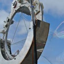
Step 10: Enjoy Mapping Magnetic Fields!


I especially enjoy seeing how, in order for the magnet to align with the field, the parts of the gimbal resolve the required rotation into the component rotations around the two pivot axes.
You can use a fog machine to make the laser beam visible, which is really impressive. I'm thinking I'll do some more long exposure photographs, leaving the laser gimbal fixed in various positions for long enough that the beams register as beams on the image.


