

Introduction: Learning to Program a Arduino - PhotoCell


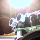
Hi there! Today I will be talking about using a photocell with programming, But first we have to Bread board all the components into the right places. do so like the photo below, or buy the Photocell kit from Aarons Robotics and read the manual in the package.
Here is what
How do Photocells Work?!
That is a very good question, Photocell consists of two special pieces of silicon joined together.
Pure silicon is naturally charged but if small amount of an impurity such as phosphorus is added, there are more free electron which make this a better conductor than pure silicon.
This is known as n-type(negative) silicon.
If a different impurity, such as boron, is added there is an absence of free electron. The absence of an electron is known as a hole and the silicon is known as p-type silicon.
When these two types of silicon are placed together it is called a p-n junction. An electric field is created between the two layers.
Sunlight is made up of a tiny packets of energy called photons. When photons are absorbed the energy causes electron to become free. They move to the negative layer and leave the junction to flow in an external circuit.
Step 1: Programing
We can now start taking about how we program this unique tool to sense light! Be sure you have the Arduino software downloaded on your computer! This can be found at : http://arduino.cc/en/Main/Software
Next Upload this code given below
___________________________________________________________________________________________________
int photocellPin = 0; // the cell and 10K pulldown are connected to a0
int photocellReading; // the analog reading from the sensor divider
int LEDpin = 11; // connect Red LED to pin 11 (PWM pin) (this is not needed to use the sensor but if you have one laying around it could add a cool affect! This can be bought at your local Radio Shack.)
int LEDbrightness; //
void setup(void) {
Serial.begin(9600); // We'll send debugging information via the Serial monitor so if you can read it without using a led
}
void loop(void) {
photocellReading = analogRead(photocellPin);
Serial.print("Analog reading = ");
Serial.println(photocellReading); // the raw analog reading
// LED gets brighter the darker it is at the sensor
// that means we have to -invert- the reading from 0-1023 back to 1023-0
photocellReading = 1023 - photocellReading; //now we have to map 0-1023 to 0-255 since thats the range analogWrite uses
LEDbrightness = map(photocellReading, 0, 1023, 0, 255);
analogWrite(LEDpin, LEDbrightness);
delay(100);
}
Step 2: Hacking!
Test it out! The Reading will show up under the serial monitor under “Tools” at the took on the arduino editor screen . You can Hack this code a Little and have it buzz with a piezo speaker! (you can put this up also at Radio Shack!)
Plug the piezo into pin 4 with the black wire or change the pin it at int piezoPin = 4;
Plug in the Photocell Circuit in at Pin 0 or change it at int photosensorPin = 0;
______________________________________________________________________________________________
int photosensorPin = 0;
int piezoPin = 4;
int val = 0;
void setup() {
pinMode(piezoPin, OUTPUT);
}
void loop() {
digitalWrite(piezoPin, LOW);
val = analogRead(photosensorPin);
val = val/2;
for( int i=0; i<500; i++ ) { // play it for 50 cycles
digitalWrite(piezoPin, HIGH);
delayMicroseconds(val);
digitalWrite(piezoPin, LOW);
delayMicroseconds(val);
}
}
here is my Video of using a little speaker to sense light
Flash Animation
_____________________________________________________________________________________
Thanks! Please contact me if you have any questions in using the Photo Cell and programming with it.


