

Introduction: Let's Build "Cubism Gal" Part 1


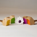


"Cubism Gal" is a wooden handbag model I designed sometime back. It was complete with leather lining and gold anodised handle. One of a range of wooden handbags I designed. I thought they'd be a niche high end winner, but people have been less than enthusiastic! When I designed them I was in my Fusion 360 infancy and really had no idea how to turn them into reality? My enthusiasm lingered though and I started on the road of equipping myself with the tools and knowledge to eventually make that happen. On my Instagram page @foreverandaday11, you'll see pics of my workshop and progress thus far. With CNC work, although not a necessity, it helps a lot if you've been at the CNC machine end and experienced the failures as a result of poor design for manufacture.
"Cubism Gal" is a complex shape and a good study for anyone wanting to progress in 3D design and CAM manufacturing and maybe learn a little about how I approach things? I'm just a self taught novice so please don't be too critical!
In this series of Instructables, I'll take you through from design to reality. You don't need to know anything about Fusion360, but it'll definitely help you to follow along if you do. It might just be the inspiration you need to make an effort to learn and become your own design master and machinist?
Supplies
A free copy of Fusion 360 download here: https://www.autodesk.com/campaigns/fusion-360-for-...
Step 1: Start With a Sketch


I'm not going to tutor you in sketch creation, be yourself and freehand your own design. I'll start with mine on the YZ plane. I want my body to have a curved face. A trick to facilitate that is, to create a sphere with a centre axis through the centre of your sketch. I'm using a 600mm dia sphere. Create an offset YZ plane behind your sketch. Create a sphere on that plane SOLID - CREATE Sphere - 600mm dia - OK
Select your sketch CREATE - Extrude change extent to To Object select sphere as object Operation New Body - OK (pic 4) You've effectively extruded your sketch faces to touch the sphere and take its shape.
Delete Body1 (sphere) and Sketch2 You're now left with a body extrusion that has a curved rear end and a flat front face. Decide on the thickness of your body keeping in mind the nett Z axis travel* of your CNC? After consideration, I'll make it 50mm deep.
" * " Nett Z axis travel is the gross Z axis clearance (150mm in my case) of your CNC less a 12mm backboard (which you'll need) and end mill projection of whatever tool you intend using. Many a great design has been canned over this limitation! I get around that by making models in layers, then glueing the seams together.
Step 2: Shaping Your Extrusion


We now need to duplicate the curved rear face on the front and adjust the body to desired depth. Right click on Body2 in the tree. Copy then Paste. Move the newly formed Body3 - 50mm. Switch off Body2 in the tree. MODIFY - Split Body select curved face of Body3 as splitting tool OK
Now you have a new Body4. Right click on Body2 & 3 in the tree and Remove...notDelete!
We are now going to extrude the faces of "Gal" by selecting sketch faces and extruding to Object and specify a cutting depth. Her left eyebrow and nose will be the furthest projection from the rear and every other face set back from them. Start with selecting the left eyelid face on the sketch. EXTRUDE - To Object select the opposing face on the body as the Object. Operation is Cut. Work your way through extruding all the faces of the sketch. I used 4mm steps.
I'm finishing the surface of my model with a 4mm dia ball end mill. Need to apply 2mm rad Fillets to all square junctions of Body4 Select contours then MODIFY - Fillet
Once the fillets are complete you can treat yourself to paint your model. Go to RENDER - SETUP - Appearance....go crazy...well done for getting this far!
Step 3: Things Can Get Tough?


Turn your model to be seen side on. CREATENew Sketch on that plane. CREATE - Project/Include - PROJECTSelection Filter is Body symbol, Geometry is your body's outline. Measure the depth of your Body4, it's 89.652mm...now that is too deep for my CNC machine to be able to comfortably machine. That means I need to split Body4 into two bodies and glue them together later.
Now this could be achieved by creating a new sketch on an offset plane at the body's rear. Then as we've done so often already extrude a face into the back of Body4. Then use that internal face to split Body4. I'll cut to the chase, "I couldn't make it happen no matter what" F360 refused to cooperate! Time for a Plan B, often required when dealing with F360. My only criticism of F360 is that the Developers are always pushing ahead with wonderful innovative improvements, but sadly there are still a lot of very basic operations with inherent bugs. Still it's free to hobbyists, so shouldn't complain.
We still need to hollow out the rear of the "Gal" , after all it is a handbag and the lil' lady needs room for all the essentials. As well, we need to form two bodies for machining ease.
Create offset plane 150mm from Origin plane at rear end of "Gal". CREATE - New Sketch on that plane. CREATE - Project/Include - PROJECT Selection Filter is Body symbol, Geometry is your body's outline. Now MODIFY - Offset a perimeter 5mm inside outside contour. Stop Sketch. Select inner face of sketch and EXTRUDE - To Object select the opposing rear face of Body4 as the Object. Operation is Cut. Offset is -20mm. You've now cut out a recess, but your body is still too deep. We'll cut off the part of the Body4 with 5mm walls.
Using the same sketch you just extruded the rear out with, this time select the entire body sketch profile. EXTRUDE - To Object select the opposing inside rear face of the Body4 cavity as the Object. Operation is Cut. You have now removed the 5mm walls of the hollowed out rear of Body4.
Step 4: It Gets Easier?


You should now be looking at a shorter Body4. Turn body to view side on and create plane and new sketch. Project body onto sketch and measure depth now. It's now around 70mm deep. Again you need to way up whether your CNC can handle this? Given that the perimeter profiles are cut out as part of the blanks creation process (different thicknesses of mdf are cut to shape and glued together to make up required depth - you'll see that in next tutorial), we only need to machine the face of the "Gal". I decide it should be OK.
Now we need to put the hollowed out rear shell back as a separate body. Go back to that rear sketch again. This time select the 5mm thick perimeter face. EXTRUDE - To Object select the opposing rear face of Body4 as the Object. Operation is New Body.. OK The rear's back on as a new body.
Turn your model to be seen side on. CREATE New Sketch on that plane. CREATE - Project/Include - PROJECTSelection Filter is Body symbol, Geometry is your body's outline. Measure the depth of your Body4, it's 64mm. 64 + 70 = 134mm deep with two bodies glued together then double that as we're talking two halves to form a handbag, and you've got 268mm deep. Getting a bit wide to be lugging around I'd suggest. We'll reduce the rear body by 20mm. Select 5mm rear edge face and right click - Press/Pull that by 20mm.
Step 5: Now for the Nuts and Bolts?


We need to give careful consideration to how we execute the machining of these bodies. The two most important issues here are:
1/ How to hold the blanks securely in place. Never underestimate the shear brute force of a 12mm end mill pushed along by a 2kw motor? It's awesome!
2/ How to identify an XYZ coordinate for setting your machine up on? Don't forget one of these bodies will be machined on both sides and will need to be flipped. Flipping a body, if not symmetric, throws registration points out.
Rename your two bodies "Front" and "Rear"
I incorporate 8mm dia hardwood dowels into the bodies. They not only hold the body secure but the centre of the dowel is a useful registration point.
Select the rear face of 5mm thickness wall and CREATE - New Sketch. Project the body onto it. 8mm dowels need a bit of meat around them for support, an extra 2mm. On the new sketch add these circular sketches. I usually sketch an 8mm dia circle anywhere on the plane and push it round with the mouse pointer to find the right position. Start with positioning two circles and then draw a horizontal line through them to be sure the centre of other two 8mm dia circles is centred on those lines. This will make your life easier later when you flip your bodies and ensure your body is parallel to the CNC machine's axis. Once all four circles are in place draw 12mm dia circles on their centre points. Then add 4mm dia fillets in corners. Trim off unwanted arcs. Now select all the newly added faces and extrude to the rear face of “Front” body. Now go MODIFY - Combine to join the 4 thickenings bodies to the “Rear” body.
After that, I look closely at my model and there are some geometry errors appearing? They shouldn’t affect anything down the line? In this instance the thickenings will be used later for pocket hinges and magnets to make the thing operate as a handbag. Always a lot to think about?
In the next installment we'll create the blanks and baseboard.

Participated in the
CNC Contest


