

Introduction: Light Sensitive Iris


This tutorial shows how to create an iris diaphragm that, like the human iris, will dilate in low light and constrict in bright light environments.
Step 1: 3D Printing


The manufacture process for the 3D printed components of this build could have its own tutorial page, and in fact, that's what I used to make them:
https://www.thingiverse.com/thing:2019585
I've included the files here for convenience.
----------------------------------
A few notes about this example, the blades (or leaves) of the iris were actually produced with a resin printer using the same files due to the limitations of the 3D printer. Also, the entire print was scaled up 10%. Getting the pieces to work together took some detail work, I ended up shaping the pieces a lot with fine sand paper, a utility knife, and a drill bit.
Other irises I investigated during this process:


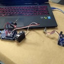
Step 2: Parts


The images show the parts you'll need as well as some of the tools and materials I used to build the model shown in the gallery:
- 3D printed iris diaphragm
- Futaba S3003 servo motor
- Arduino UNO micro crontroller
- Light Dependent Resistor: dark resistance 1M ohm / light resistance 10 ohm – 20k ohm
- 10k ohm analog potentiometer
- 500 ohm resistor
- PCB (printed circuit board)
- headers (five)
- wire: black, red, white, and yellow
- dupont connector wires (two)
- soldering iron (and solder)
-multimeter
- wire snips
-------------------------
The structure that houses this prototype was made with MDF, 3/4 inch plywood, wood glue, hot glue gun, stiff wire (from a coat hanger and a paper clip), as well as various drills and bits, a table saw and a band saw, power sander and lots of trial and error. The object from the photos is the third iteration.
Step 3: Building the Circuit/Housing


I had a "chicken and egg" style conundrum while designing this aspect. Since I don't have experience with electronics schematics, I prefer to think about the circuit in terms of its actual configuration, or pseudo-schematic. I found that the architecture of both the MDF/plywood housing and the wiring were constraining each other in unexpected ways. I tried to come up with something that was visually simple and self contained.
-The potentiometer was a late stage idea during the brainstorming to add a "sensitivity" adjuster, since ambient lighting conditions can vary greatly, the potentiometer and resistor together take the place of a normal resistor in the voltage divider aspect of the circuit. I cannot go into detail about this because I don't really know how it all works.
-The vertical part of the housing (made from MDF) is at a slight angle. In order to rotate in the same plane as the iris, I used a table mounted belt sander to create the same angle on the wooden servo mount that I glued to the plywood base.
-I also found that the servo preferred to lift the MDF board right off the base instead of articulating the iris, so I added a wire retaining staple that inserts at the front to lock the two pieces. While I was at it, I added pins for the Arduino board out of the same wire. The wire connecting the actuator arm to the servo is a paper clip, by the way.
-The iris fits snuggly into the MDF, but even still I added a bead of hot glue to prevent the entire housing from rotating in the socket instead of just the actuator arm. This necessitated more precise alignment of the servo lever arm than I had expected. What is likely obvious to many using this tutorial, though unexpected to me when I began, was that the rotation of the servo and the rotation of the iris is 1:1. I had to make a small plastic arm extension for the servo to achieve the same radius as the iris actuator arm. The code originally took full advantage of the servo's rotational potential, but I ended up measuring the actual rotation of the iris, then, through trial and error, found a custom value for degrees of rotation of the servo that achieved an interesting effect.
- Many of the important wiring connections are hidden underneath the PCB in the images. I forgot to take a picture of that side of the PCB before I hot-glued it to the MDF. This is for the best, since no one should copy the mess I hid underneath that small piece of PCB. My objective for the PCB was to have headers for the 5volt, Ground, and servo connectors so that the pieces could easily come apart for unforeseen troubleshooting in the future, a feature that came in handy. I indicated the proper orientation for header connectors with a piece of masking tape on the MDF beside the PCB, though I suppose I could have written directly on the MDF...it seemed like the right thing to do at the time.
Step 4: Code

#include // servo library
Servo serv; //declaration of servo name
int sensorPin = A1; // select the input pin for LDR
int sensorValue = 0; // variable to store the value coming from the sensor
int timeOUT = 0; //variable for servo
int angle = 90; //variable to store pulses
void setup()
{ serv.attach(9); // attaches the servo on pin 9 to the servo object Serial.begin(9600); //sets serial port for communication
}
void loop()
{ sensorValue = analogRead(sensorPin); // read the value from the sensor
Serial.println(sensorValue); //prints the values coming from the sensor on the screen
angle = map(sensorValue, 1023, 0, 0, 88); //converts digital values to degrees of rotation for the servo
serv.write(angle); //makes servo move
delay(100);
}

Participated in the
Make it Move Contest


