

Introduction: Light to Enhance Glass/Crystal Awards Using ATtiny85 Ws2813


If you want to learn about ATTiny and hardware interrupts this is a very good project. This project also runs 28 or more RGB LEDs (WS2813) from the ATTiny85 and 3 AAA batteries. Its a fun way to make something "GLOW"
At work they occasionally give out glass/crystal awards for outstanding work. I thought it would be fun to use LEDs to "Light it Up!!!". This project needed to be small and run on batteries. I used an ATTiny85 and 3 AAA batteries along with a segment of WS2813 the length of the base of the award. I also wanted the ability to change the colors of the LEDs on the fly without reprogramming the ATTiny.
In this project I was also able to use the FastLED library and a push button with a hardware interrupt to change the LED colors/Palette. Hardcore people would say I need to work on my debounce on the button because it jumps, but I prefer to think of it as "Random Color Palettes".
So ... "Why an ATtiny85 and not an arduino?" This project only needed a single input and output. The ATTiny has an internal 8MHz clock and an operating voltage from 1.8 - 5.5V for ATtiny25V/45V/85V. The LED Strip WS2813 has a voltage requirement of +3.5~+5.3. The project works great with 3 batteries. Also the ATTiny is about $2-$3 which I don't mind making part of a permenant project like this one.
In this project I will show you:
- How to setup the arduino as an ISP (In System Programming)
- How/Why to burn a boot loader to an ATTiny85 Loading (firmware) program on the ATTiny85
- Change a hardware interrupt to pin and push button
- Solder the components on a strip board.
Note: In this project I solder and use strip board. That is optional, just use a breadboard and lots of wires. I also use a 3D printer to make a thin stand to hold the LED strip which is also optional. I hope you enjoy this as much as I did making it.
Step 1: Parts List
There are parts needed to program the ATTiny85 microprocessor and parts to build the project. I will list them separate since you can reuse the programmer once you have finished that step.
- ATTiny85 Programmer.
- Arduino Uno Breadboard. (small or half size or prototype shield all work great).
- wires (male/male).
- 10uf Electrolytic Capacitor
- Optional 220 ohm resistor and LED to test the program.
3D Printer (optional)
Solder Iron/Station (needed unless you are just putting this on a breadboard).
Project Parts (I purchased most parts from https://www.taydaelectronics.com
- 8pin socket ( 3 cents )
- Push button -TACT SWITCH 6X6MM 4.3MM THROUGH HOLE ( 4 cents )
- small strip board. (66 cents )
- ATtiny85 - Around $2 - $3 each.
- I bought 5 for $10 on Amazon.
- 3 AAA battery holder ( 26 cents )
- Resistors 470 ohm ( 1 cent )
- 10k ohm ( 3 cents )
- LED Strip (WS2812b or WS2813) I used a section of a 144led/meter strip. (amazon for $22)
- Wire - 22 AWG wire - 3 colors work best. probably 1' of each color
Step 2:
Step 3: Light to Enhance Glass/Crystal Awards Using ATtiny85 Ws2813
If you want to learn about ATTiny and hardware interrupts this is a very good project. This project also runs 28 or more RGB LEDs (WS2813) from the ATTiny85 and 3 AAA batteries. Its a fun way to make something "GLOW"
At work they occasionally give out glass/crystal awards for outstanding work. I thought it would be fun to use LEDs to "Light it Up!!!". This project needed to be small and run on batteries. I used an ATTiny85 and 3 AAA batteries along with a segment of WS2813 the length of the base of the award. I also wanted the ability to change the colors of the LEDs on the fly without reprogramming the ATTiny.
In this project I was also able to use the FastLED library and a push button with a hardware interrupt to change the LED colors/Palette. Hardcore people would say I need to work on my debounce on the button because it jumps, but I prefer to think of it as "Random Color Palettes".
So ... "Why an ATtiny85 and not an arduino?" This project only needed a single input and output. The ATTiny has an internal 8MHz clock and an operating voltage from 1.8 - 5.5V for ATtiny25V/45V/85V. The LED Strip WS2813 has a voltage requirement of +3.5~+5.3. The project works great with 3 batteries. Also the ATTiny is about $2-$3 which I don't mind making part of a permenant project like this one.
In this project I will show you:
- How to setup the arduino as an ISP (In System Programming)
- How/Why to burn a boot loader to an ATTiny85
- Loading (firmware) program on the ATTiny85
- Change a hardware interrupt to pin and push button
- Solder the components on a strip board.
Note: In this project I solder and use strip board. That is optional, just use a breadboard and lots of wires. I also use a 3D printer to make a thin stand to hold the LED strip which is also optional.
I hope you enjoy this as much as I did making it.
Step 4: Parts List
There are parts needed to program the ATTiny85 microprocessor and parts to build the project. I will list them separate since you can reuse the programmer once you have finished that step.
ATTiny85 Programmer.
- Arduino Uno
- Breadboard. (small or half size or prototype shield all work great).
- wires (male/male).
- 10uf Electrolytic Capacitor
- Optional 220 ohm resistor and LED to test the program.
3D Printer (optional)
Solder Iron/Station (needed unless you are just putting this on a breadboard).
Project Parts (I purchased most parts from https://www.taydaelectronics.com)
- 8pin socket ( 3 cents )
- Push button -TACT SWITCH 6X6MM 4.3MM THROUGH HOLE ( 4 cents )
- small strip board. (66 cents )
- ATtiny85 - Around $2 - $3 each. I bought 5 for $10 on Amazon.
- 3 AAA battery holder ( 26 cents )
- Resistors
- 470 ohm ( 1 cent )
- 10k ohm ( 3 cents )
- LED Strip (WS2812b or WS2813) I used a section of a 144led/meter strip. (amazon for $22)
- Wire - 22 AWG wire - 3 colors work best. probably 1' of each color
Step 5: Setup the Arduino As ISP
This is a common project in itself and if you search Instructables there are many people that have very elegant solutions. (search for Arduino as ISP) Since the goal here is to just load a program and bootloader on a ATTINY85. We will add the blink program to verify everything before moving to the rest of the project.
Steps:
- Install the Arduino software on your PC. https://www.arduino.cc/en/Main/Software
- Connect Arduino to the PC and load the Arduino as ISP software.
- Connect Arduino with USB cable.
- Start the Arduino Software call an IDE
- Under the "Tools" menu - pick Board: Arduino/Genuino Uno
- Under port pick the port the Arduino is connected.
- Click on File and Examples.
- Click on 11. Arduino ISP

- Click on "Tools" menu then set the "Board:" to Arduino/Genuino UNO as the board being programmed.
- Make sure the Arduino is found under the Port Setting.
- Click on the "Sketch" menu then upload.
- You now have the arduino loaded as a Programmer. This will allow you to now program the ATTINY85. The first thing to do before we program the ATTINY85 is to get the board definitions loaded for it.
- Click on "File" then "Preferences"
- In the text area next to "Additional Board Managers URLs:" put: http://drazzy.com/package_drazzy.com_index.json
- click ok
- Next click on "Tools" menu
- then go down to Boards.
- Click on "Board Manager..." on the menu.
- Type in ATTINY on the Search bar.
- Pick ATTinyCore by Spence Konde.


You are now ready to wire up your programmer!!!
Step 6: Make Programmer for ATTiny85
Now you have the drives installed and are ready to create the ATTiny installer. This requires you to place the ATTiny85 on the breadboard. It's important to note the top of the chip has a dot in the upper left corner. If you put the chip in the board upside down it will heat up. If it gets to hot it will be destroyed, so check the orientation before you add power.

I wanted explain the diagram. The ATTINY pins are 1-4 on left and 8-5 on the right (see diagram). The Arduino Program/firmware actually calls the pins different numbers. The diagram shows the Arduino internal names as PB0-PB5.
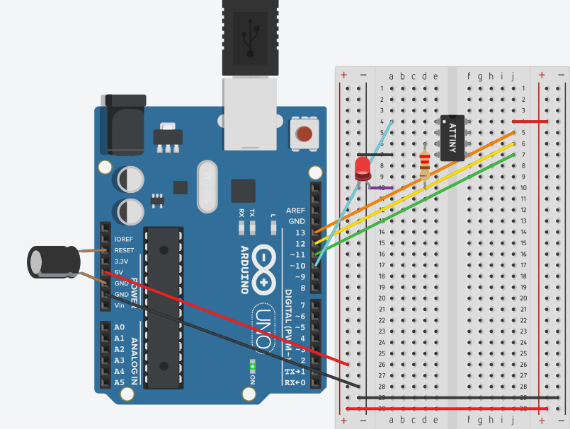
Wire up the Arduino ISP to a Breadboard.
- Set the breadboard next to the Arduino.
- Put the ATTiny85 on the board and verify the top is where you expect it.
- See diagram on pin locations. Make sure the Chip straddle the groove in the middle of the board.
- Connect 5V from Arduino to pin 8 on the ATTiny.
- Connect Ground from Arduino to pin 4 the ATTiny.
- Arduino Pin 13 to ATTiny pin7.
- Arduino Pin 12 to ATTiny pin6.
- Arduino Pin 11 to ATTIny pin5.
- Arduino Pin 10 to ATTiny pin1 (reset on ATTiny85).
- In addition to the minimum I add a 220ohm resistor from pin 2 to a spot below the ATTiny85. Then connect an LED from Ground to the Resistor.
- The last Step is to put the electrolytic capacitor from ground to reset on the Arduino. (note that electrolytic capacitors have a minus sign (-) on one side that goes to ground.
Program the ATTINY with Blink< 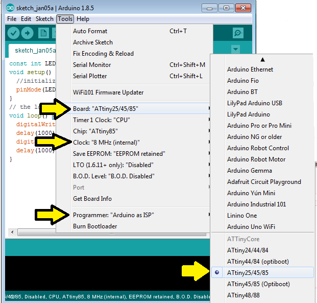
- Start the Arduino IDE
- Attach Arduino
- Make sure the board selected is still the ATTINY85 Clock: 8Mhz (internal)
- Verify the Arduino Com port is selected.
- Set the Arduino Programmer as "Arduino as ISP"
- Copy the below blink sketch and put in Arduino ISP. (or get it from GitHub here:)
<strong>const int LED=4;
void setup() {
  //initialize pin 4
  pinMode(LED, OUTPUT);
}
// the loop function runs over and over again forever
void loop() {
  digitalWrite(LED, HIGH);   // turn the LED on (HIGH is the voltage level)
  delay(1000);               // wait for a second
  digitalWrite(LED, LOW);    // turn the LED off by making the voltage LOW
  delay(1000);               // wait for a second
}
</strong>
After loading the blink program, the LED should blink once a second (1000 milliseconds). If the blinks are longer than a second you should burn a new bootloader on the ATTINY. (if the led doesn't blink you may need to turn it around).
To burn a new boot loader
- Attach Arduino to PC with USB Cable
- Click on the "Tools" Menu
- Verify Programmer is still set for "Arduino as ISP"
- Click Burn Boot Loader

Step 7: Load the ATTiny85 With the Program/Firmware
Before we can load the program we must first add the FastLED library.
To add the library, click on the "Sketch" menu. Next click "Include Library" then pick Manage Library on the top of the list.

Search for the FastLED module and install it.

Now you are ready to fetch the file from Github here:
Open the file in arduino IDE, ,make sure the programmer is set to Arduino as ISP.
Make changes the code changes as needed:
#include <FastLED.h>
#define LED_PIN     0  //WS2812B data line. (two wires for redundancy).
#define NUM_LEDS    28
#define BRIGHTNESS  80
#define LED_TYPE    WS2812B
LED_Pin is PB0 on the ATTINY. Its the data pin that is connected to the LED strip.
NUM_LEDS should be set to the number of LEDs in the strip.
LED_TYPE should be the type of LED Strip you are using.
Hardware Interrupts
I wanted to explain the interrupt code since this is the interesting part of the program. This processors has a pin (PB3) connected to a button. When the button is pressed we want the program to stop what its doing and change the colors of the LED strip. This can work because the program loops through the palettes and if we change the pallet the program will keep looping without stopping.
First we set the interrupt on PB3. This happens with this code.
    GIMSK = 0b00100000;    // bit 5 turns on pin change interrupts
    PCMSK = 0b00001000;    // turn on interrupts on pins PB3
    sei();                 // set Global Interrupt Enable
The interrupt call a routing called ISR. There is only one routine no matter how many pins you set in PCMSK.
The ISR subroutine I use increments a counter this value is incremented every time the button is pressed and the pallet is set based on value.
ISR(PCINT0_vect)
{
    value ++;             // Increment volatile variable
    switch(value){
       case 1:  currentPalette = RainbowColors_p;         currentBlending = LINEARBLEND; break;
       case 2:  currentPalette = RainbowStripeColors_p;   currentBlending = NOBLEND;  break;
       case 3:  currentPalette = RainbowStripeColors_p;   currentBlending = LINEARBLEND; break;
       case 4:  SetupPurpleAndGreenPalette();             currentBlending = LINEARBLEND; break;
       case 5:  SetupTotallyRandomPalette();              currentBlending = LINEARBLEND; break;
       case 6:  SetupBlackAndWhiteStripedPalette();       currentBlending = NOBLEND; break;
       case 7:  SetupBlackAndWhiteStripedPalette();       currentBlending = LINEARBLEND; break;
       case 8:  currentPalette = CloudColors_p;           currentBlending = LINEARBLEND; break;
       case 9:  currentPalette = PartyColors_p;           currentBlending = LINEARBLEND; break;
       case 10: currentPalette = myRedWhiteBluePalette_p; currentBlending = NOBLEND; break;
       case 11: currentPalette = myRedWhiteBluePalette_p; currentBlending = LINEARBLEND;  break;
       default: value=0;
    }
}
Step 8: Building the Board.
If you are going to use a breadboard or use a strip board you must refer to the pinout of the attiny85.
These pins are used if its soldered into a stripboard or on a breadboard.
- Pin8 is your voltage source. 4.5 v from batteries.
- Pin4 is ground or the - side of the batteries.
- Pin5 (PB0) goes to the data line on the leds. the WS2812b recommend a 470Ohm resistor between the pin and leds.
- Pin2 (PB3) is the pin our hardware interrupt is setup on. This also has a 10kOhm resistor to ground.

If you use strip board you need to use the 1/8th inch. I found it easier to solder in the socket, then remove the copper tracing between the pins. I use an ohm meter to make sure i got all the copper between the pin.

- First solder in an 8pin socket into the board so the ATTINY85 may be removed and reprogrammed.
- Remove the copper tracings between the pins with 1/8th inch drill bit.
- add the resistors.
- the 470 ohm from pin 5 (PB0) to the data in on the LEDS. I run two writes on the WS2812b
- the 10k ohm goes from ground to the pushbutton.
- + voltabe from the battery goes to the PIN8 on the attiny and the pushbutton


Connect the LEDS:
In the abover diagram the purple wire goes to the data on the led strip, the red wire to 5V line and the black wire goes to ground.
Step 9: 3d Printed Parts
I created a flat holder to put under my award, there is a groove that the LED strip fits. Since my 3D Printer doesn't print more than 6 inches I separated the parts in half.

I then created a small holder that would hold the batteries and the circuit board. I printed two of these and they fit over the battery and the board.

Although your project my be different from mine I will post the .stl files to give you a starting point.

Participated in the
Make it Glow Contest 2018


