

Introduction: Make a Custom Box Mod (e-cig)


A box mod is the battery box which powers the atomizer in an e-cig device. I refer to my mod as a hybrid boxfet, in that Im using a mechanical button, which is glued onto an aluminium rivet. The rivet end presses a lever style micro switch soldered on the gate of a IRLB3034 mosfet which does the heavy duty current carrying.
This is an unprotected mod, meaning there are no electronics monitoring excessive current draw which can switch off power under fault conditions.
Safety was my first design consideration and the final product doesnt get hotter than 35 deg C.
- Never leave box mods in a parked car in the sun, interior temps can soar creating a dangerous environment for your device.
- Never use a battery not designed for ecigs, ie laptop low drain types, my Efest 18350 can do 10.5A continuously.
- Never use a switch for the main power that cannot handle the max rated battery current.
- Always use internal wiring that can safely handle the batteries max rated current.
- Best practice is to include some form of fuse in the circuit, mine uses an auto-reset 10A fuse.
- Best practice is to use a capable power mosfet to handle the high currents safely, mine can do in excess of 195A.
- Always know the coil resistance of your atomizer, too low coil resistance can draw excessively high currents which can damage batteries and melt the wiring insulation creating a hazardous situation, usually in your pocket.
An excellent website that will assist with box mod design on the electrical side is Steam Engine calculations.
The mosfet can switch 195Amps, battery contacts are copper strips, the main power wiring is two twisted solid core 1mm dia bare copper wire that can handle 20A in an enclosure, all backed up with a 10A auto resettable fuse, looks like we're good to go.
Step 1: Custom Fire Button


I happened across these mother of pearl beads and knew they were a box mod firing button, everything else was pretty much designed around them.
The two halves were epoxied together and had to be heated up to separate them, which changed the colors.
Next the bead was CA glued to a wide head rivet running through a brass tube in the wood box. Most any lever style micro switch can be used seeing as it isn't carrying high amps, mine is a 1A 125V model.
The large button overhang (button surface wider than shaft diameter) which was causing binding, this I thought I'd fix using a piece of silicone tube as a return spring. This created a hard to operate button and so I wound a very cool stainless steel spring from fishing line leader wire. The problem of sticking remained and I finally desoldered the switch off the mosfet and glued in into a position where the rivet would act directly on the micro switch lever.
Step 2: Front Design Engraving


I originally used aluminium but it was hard to follow a line while engraving as the engraver tip seemed to wander off as soon as it bit into the soft metal.
Next up was 0.9mm stainless steel sheet, I used a paper template but the main problem is trying to position a blurred vibrating tip on a 4pt font. I have newfound respect for tattoo artists.
I used a new scotchbrite pad to brush the vertical lines, then chucked a round piece into the drill press to do the circular lines for the sun, next I engraved the eagle outline and filled it in with black hammerite paint.
Lastly I covered the entire plate with a 2 part epoxy, Heritage Liquid Glass, which created a slight rounding of the edges.
Magnets were CA glued to the back of the SS plate.
Alone and without his nest shall the eagle fly across the sun.
from The Prophet by Kahlil Gibran
Step 3: Wood Cutting


I started with a block of Pau-Marfim and dremeled out the internal shape for the electronics and battery.
The drill press was essential for perpendicular holes. I also drilled four holes for steel nuts at the corners for future adjustments in case of thinner magnets of thicker doors, they can be pulled out with a M3 machine screw. The holes were set in 10mm from the edge so that pressing the nuts in wouldn't split the wood.
Once finished with the dremel, the block was cut to size and sanded to 400 grit sandpaper.
Next the brass base plate for soldering the 510 connector to was cut out and shaped. It was drilled and the hole positions marked on the wood.
Step 4: On Switch and Voltage Monitor


A simple circuit to monitor the batt voltage will ensure safe device use.
I used the BATTERY MONITOR MkI circuit over at Talking Electronics the 2nd version called single li-ion cell monitor.
I find that I can detect a drop in vape performance once the batt gets to 3.7V and I subsequently then recharge it.
The green led also acts as a reminder that the device is on and not in safe mode with no power on the firing button, meaning the button could be operated if tossing it into a bag with other items.
It was easier to drill holes for the leds and insert them from the inside of the box, not having a gaudy red and green led on the outside is a design bonus.
Step 5: Assembly and Electronics


I started with installing the 510 connector, next was the fuse and the pos batt terminal. Once their positions were known they were all soldered together.
The batt contacts were cut out of brass sheet, pos soldered to the resettable fuse and neg to the source leg of the mosfet.
Not all mosfets are suitable in this application, low on gate resistance is desired for minimum losses due to heat. A low gate threshold voltage is also desirable in order for the mosfet to switch on properly, for a single li-ion cell, a 1~2.5V Gate (th) voltage is best.
A 2.5v ~4v gate voltage is fine for 2 cells in series, ie 7.4v and higher, a typical example is the capable IRF1404, which performs very poorly if at all on a single 3.7V li-ion cell.
The on/off switch was installed with the leds pressed into the holes and sealed with clear nail varnish, lastly the mosfet and neg batt contact was installed and the micro switch glued in.
Step 6: 510 Brass Mount


Solid brass bar was used to solder the 510 connection too.
Once soldered all places were covered in silicone grease so that the whole device could be suspended in a jar with ammonia solution to create the patina. It turned out darker than expected once it was covered in 3 layers of clear nail polish.
I used the #18 Purple formula I found at Science Company.
I didn't find Ammonium Chloride locally and left it out, I used Falksalt Natural sea salt for the sodium chloride component, brushed it on as advised and left it fuming in the ammonia overnight.
Step 7: Finishing


I used Woodoc 20 polyurethane thinned 50/50 with turps as a stabilizing agent.
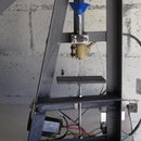
A pyrex mixing bowl served duty as a vacuum chamber with a matsushita rotary piston aircon compressor creating the vacuum.
Caution is needed in the initial stages so that varnish doesnt get sucked into the compressor as the fluid tends to foam up a lot.
The whole process took about 4hrs with many cycles of vac and then release. Once dried overnight the block was followed up with 2 coats unthinned.
On a 700ma 18350 battery, I get about 2 tank fills with a Kangertech mini ProTank 3 running a 1.5 ohm coil.
Having a nitecore charger on hand and being able to swop out the cells easily was a catalyst for this small design.
The end product feels good in the hand and I'm happy with this version, the magnets give a satisfying click when closing the box, they do have a tendency to pop off though.


