

Introduction: Making Profiles From CAD DWG/DXF Files


Beware of taking sketch information from any CAD drawings because the information is only as good as the original drawing.
A sketch may be under-dimensioned like the one we are going to work on. Or drafters may simply change the dimensions on the drawing rather than making actual changes to the lines when being rushed to get a project completed and out the door. I have done this myself. Simply explode the dimension and change the text. Management may not have the same commitment to drawing accuracy as the drafter would like and force last minute corrections to a drawing that override the inherent drawing information.
Most 2D CAD systems do not have constraints to do such things as force curves into tangency, the accuracy of curve transitions is left to the skill and experience of the drafter. With the bulk of production drafting commonly being done by employees in an entry level positions, the experience of the drafter may be minimal.
Additionally, consistency between views done with 2D drafting tools is left to the skill of the drafter. It can be common to encounter drawings that have discrepancies between view orientations, or even reflect different phases of a designs evolution.
So, take information from a 2D CAD drawing with care, because it can be faster and better to simply draw an Alibre sketch from scratch using the dimensional information provided by the drawing.
That said, let's create an Alibre Catalog Feature from a .dwg or .dxf file.
Step 1: Download

Download the .dwg or .dxf file provided by the vendor or supplier. I am using Interstate Lumber profile IL720 from their online catalog.
Step 2: Import the 2D Drawing

Choose File > IMPORT the 2D CAD drawing into an Alibre drawing to allow the extraction of the drawing information. It is better to extract information from Modelspace rather than Paperspace when possible. Check the Design Explorer for the available selections. This example only had Modelspace. More complex drawings may have both.
Step 3: Explode It!


If the profile is provided as a Symbol, explode the symbol by hovering over the profile so at it is highlighted, right click and select Explode Symbol. You will now be able to highlight each line individually and copy it to an Alibre Part sketch. Sometimes multiple symbols need to be exploded to obtain all the profile information.
How can you tell if a profile contains symbols? Typically the whole profile is a set of lines and arcs connected as a Block (as in AutoCAD). In our example, several line segments only are highlighted when the pointer hovers over one of the segments. This is the group or Block that we will Explode.
Step 4: Activate Sketch

Activate Sketch on Sheet in the drawing to allow selection of individual drawing elements, so that they can be copied.
Step 5: Select the Parts to Copy.

Select the lines and arcs in one of two ways: After selecting the first element of the profile, press and hold down the Shift key so that subsequent selections are added to the selection rather than replace the original selection. Try to get all the elements composing the profile selected and highlighted before copying the selection. If you need to unselect a line or arc, just left click select that element again to remove it from the selection. Often it is better to use a selection box, where you press and hold the mouse button while dragging a box around the entire selection area (similar to a zoom window command). You can delete any undesired elements from the selection once pasted into the part sketch.
Step 6: Copy It.

When all the desired elements of the molding profile are selected, copy the selection by using EDIT > COPY from the menu. This menu selection is preferred to the CTRL+C keyboard copy command as the latter does not always perform the desired copy (a quirk of Windows).
Step 7: Open a New Alibre Part.

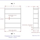
Open a new Alibre Part file. Select the XY reference plane in the Drawing Area, or from the Design Explorer. Activate 2D Sketch on the XY reference plane as it is best when manipulating Catalog Features to have the sketch in this orientation. Once the Catalog Feature is created, the molding profiles can then be inserted on the YZ plane, where the Front view orientation provides a view of the molding profiles, the End View provides a cross section, and the single Isometric View provides the best representation of the profile. Consistency is important when creating models so that others, as well as yourself, can work quickly with parts.
Step 8: Paste It.

EDIT > PASTE from the menu to paste the copied line drawing information from the 2D CAD drawing. Again, using the menu to paste has proven more reliable than the keystroke combination. IMPORTANT: Do not be surprised if the drawing information does not appear within the current viewing area. Copied elements are often pasted outside the current screen boundaries because the location on the plane is based on the original drawing location from the origin.
Step 9: Stabilize It.

Select Orient to Sketch Plane if required, and press the Home key to zoom the pasted drawing information within the bounds of the display. The lines pasted may be located near the origin, or may be located a great distance away. Do not attempt to move the profile information just pasted or the coherence of the molding profile may be destroyed. That is, parts of the profile drawing may shift away from the others as 2D CAD drawings do not maintain the element endpoint constraint conditions original defined in the drawing. An "object snap" in 2D CAD is a positioning tool, and is not an endpoint coincident constraint.
Step 10: Constrain It.

Fully constrain the new sketch figure to keep all the geometry together when the Catalog Feature is inserted and shifted within a part. You may have to come back and add more constraints to a sketch after testing your new Catalog Feature, if you find that it does not remain intact while being located in a part file. It is best to shy away from the Vertical and Horizontal constraints, and use the Perpendicular and Parallel constraints instead. This will allow sketches to be rotated or mirrored to different orientations as required. You may want to omit some Tangent constraints from curves until they are fully dimensioned. Forcing some tangencies can distort a sketch unless dimensioned beforehand.
Step 11: Dimension It.

Completely dimension the sketch to make sure that the sketch is fully constrained. This will assure it won't come apart while being used or moved. Make sure all arcs are fully constrained or dimensioned as well so that they remain in relative position while the Catalog Feature is being rotated and shifted within the destination part file.
Step 12: Analyze It.


Now Analyze the Sketch with Sketch > Analyze, to heal any open loops because of lack of endpoint constraints due to the sketch originating from 2D CAD. Heal any other problems that are possible. Sometimes the Heal button will not be active for a specific problem listed. First deal with any problems where the Heal button is active, and then return to these other problematic conditions afterward. Often the Heal button will activate for those problems after the others have been dealt with. Fix any other problems that the Analyze tool can not automatically resolve, and then any drafting errors encountered in the source file. Often curves are not tangent, or lines are overlapping from not using object snaps.
NOTE: I Analyzed the profile before Constraining and Dimensioning so that you could see how the object snaps do not guarantee endpoint position as discussed in Step 9.
Step 13: Orient It.

Once fully constrained and dimensioned, consider the orientation of the profile for use as a Catalog Feature. In general, it is best to remain consistent with the front side of the profile oriented to the Left, and appropriate geometry oriented towards the top. This will create a profile that has a good visibility in the Isometric orientation when inserted onto the YZ reference plane. Avoid creating molding profiles that when inserted on the YZ plane, where the Isometric or Front orientation views the back or bottom of the molding. Use the Rotate, Mirror with copy, or other tools to change the orientation of the molding profile as required. There will be some circumstances where an alternative orientation will also need to be created in order to use the molding where the back and bottom are reversed (laying down rather than standing up). In this case, you will need to make a second copy of the molding profile and change the orientation to suit the intended use. Try again to keep the profile information oriented to the Left and Top. You can simply create 2 different orientations from the outset as profile, and reversed profile.
NOTE: Now that the sketch is stable and in the orientation that we want. Hide the distracting dimensions and constraints by toggling off their icons in the top toolbar. Leave the profile where it is. If you move it (say to the origin) then as a Catalog Feature it will be inserted locked to the origin. You want the flexibility to move the feature wherever you want.
Step 14: Rename It.


Rename the Sketch to identify the profile, because it is the sketch name and not the saved filename that is used when the Catalog Feature is inserted into a Part file. The main image in Step 16 shows the name as Sketch 1>. In this case it would be IL720.
Also, rename all the parameters in the Equation Editor with an identifier at the beginning of the parameter name. We use a vendor abbreviation and profile identification followed by an underscore, inserted at the beginning of each parameter name. This provides rapid identification of parameters associated with a particular Catalog Feature when working with the Equation Editor in the destination Part file.
Step 15: Create a Catalog Feature.


The two images used for this show a different profile, but the process is the same.
Create the Sketch Catalog Feature by highlighting the sketch, and then selecting Feature > Save Catalog Feature. You can also select the sketch after the fact, if the appropriate sketch is not highlighted before hand. We often save the Catalog Feature with the same name as the Part File. Only the Catalog Feature will be visible in the Insert Catalog Feature dialog when browsing to a folder containing both a part and Catalog Feature. Our naming convention consists of the vendor and profile identifier, followed by the work Profile to indicate that this is a Catalog Feature containing profile information.
Step 16: Mold It.


You now have a Catalog Feature you can insert on the YZ reference plane to create your molding.


