

Introduction: ARCA (Adorable Remote Controlled Android)


This instructable was created in fulfillment of the project requirement of the Makecourse at the University of South Florida (www.makecourse.com).
ARCA is an Adorable Remote Controlled Android that is incredibly fun to build and to play with. The goal of this project was to create something that anybody can understand and relate to by creating a robot that is both adorable and functional.
The robot functions by displaying different emotions on an 8 by 8 LED matrix, these emotions include joy, sleeping, love, anger, silly, and looking up, left, and right. The robot also operates like an RC car and can go forward and turn left or right. The robot goes forward by activating both wheel motors, turns left by turning on the right motor, and turns right by turning on the left motor. The design is very simplistic but it just works, and I wanted to have a heavy focus on the programming of the Arduino since I am a programmer at heart.
The latest versions of all the files used in this tutorial can be found on my Github ARCA Repository.
Step 1: Parts List and 3D Printing


Parts for this project can either be 3D printed or purchased online. When thinking of the assembly, I wanted to make efficiency key and also try to not (quite literally) reinvent the wheel. The 3D printer used for this project was a Makerbot Replicator, if you want to make sure that your 3D prints are consistent with mine then use this printer.
Structural Components
- Box with holes in the sides for the wheels and arms
- Box lid with holes for back wheels and a hole for the IR sensor
- Left arm
- Right Arm
- Axle for the two back wheels
- two axle connectors to connect the lid to the axel
- 4 wheels (motors also included in this link)
- Small screws (to fit in the motors)
Electrical Components
- Arduino Uno
- Small breadboard (I bought the Arduino kit and it came with it)
- Two MAX7219 Red Dot Matrices with MCU Control
- Infrared reciever and remote
- Two TIP 120 transistors
- Connecting wires (I used a lot of male to female wires as well as male to male, and recommend getting long wires as opposed to short wires)
- one 220 ohm resistor
- Two gear motors
- USB connectable power packs (the portable ones used for cell phones)


Step 2: Assembly


Structural Assembly
The 3D printed parts will likely need some cleaning up, and I recommend sanding it with a fine grit and using acetone (nail polish remover) to remove any residue of glue used in the 3D printing process. Some of the parts may not fit perfectly, and it was necessary for me to sand the axle to be perfectly round and fit through the holes properly.
The wheels need some slight adjustment, they needed to be drilled more to fit the dimensions of the axle in the back and the screws in the front. Use a 6mm drill bit to drill through the holes in the wheels to bore out bigger holes in the wheels.
For this assembly I used a variety of glues, but I found that liquid concrete (modeling glue) was the best for hold despite a long drying time but epoxy was best for things you need to dry quickly and hold well, despite being messy.
The rest of the assembly is pretty straight forward:
- Attach the axle holders to the back of the box lid, using epoxy to seal
- Run the axle through the axle holders
- Glue the wheels to the axle using liquid concrete
- Put the arms through the upper holes, and glue to the arm holder using epoxy
- Screw the lid of the box into the box
- Use electrical tape on the bottom of the box where the wheels are
Electrical Assembly
The front wheels are attached directly to the motors, and you need to use a small screw in the motor to make it long enough to fit through the hole in the robot on each side. There should be a small hole in the rotating peg of the motor and you can screw in the screw there and glue the head of the screw into the wheel after pushing the screw through the hole in the box.
The back of my breadboard had a sticky backing, but you can use electrical tape to adhere it if yours does not. Electrical tape was also used for attaching the electrical components not in the board, for safety reasons. The MCU's with the LED displays were attached to the back of the eye sockets using electrical tape and the motors were also attatched to the sides of the box close to the holes using electrical tape. I used red electrical tape to make it more invisible, just in case, and I recommend using an electrical tape with a similar color to your version of ARCA.
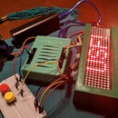
The breadboard and pins are set up like this Fritzing image. If you want to add more to this diagram to customize ARCA you can download the Fritzing file in my Github repository and edit it to your heart's content.
I attached the wires to the loops in the gear motors by bending the wires around the loops, to keep them attached. It would probably be a better idea to solder these connections if you have access to soldering iron, but this is an easy solution if you don't have one.
The power pack is attached to the same cord used to connect the Arduino to the computer to download your program, and this is just loose in the robot so it can be easily removed and charged.
Step 3: Programming

Here is the code you can upload to your ARCA to get it to function exactly like mine, you also need the following two libraries to use the code.
For the sake of clarity and customization, however, I will walk you through my code. Feel free to skip this step if you are not customizing your robot or do not plan on changing the emotions.
First, I include two libraries for use in my code, allowing me to use the functions and objects of these libraries. I am also defining my pins here. If you decided to make your pins different than my set up in the previous step, make the changes to your code here with the proper pins.
Next, I defined the emotions, declared the necessary objects for the IR sensor and the 8 by 8 LED displays, and defined some global variables. The emotions are declared in a byte array, where each of the hex numbers in the array represent the rows in the resulting 8 by 8 display. To create your custom emotions, I recommend drawing out the emotion that you wanted in an 8 by 8 grid, and then writing out each row 8 bit binary number where the light off is a 0 and the light on is a 1, and then create a hexadecimal number from that and put it in an array of length 8. I have also defined some global variables to use in the loop; the variables for the blinking mechanism and the pointers to store the emotions and set them to start out at neutral.
Now we get to the set up loop, where I turn on serial monitoring for the sake of testing, and this should be helpful to test your code with different IR remotes. Then, I initialized the left and right eye objects using functions from the LED control library. I also set the gear motor pins to output and started the IR receiver.
In the loop, it essentially waits for the IR signal to change the status quo of the robot. So if an IR signal is received and it matches up with one of the codes from a specific button, then that if statement is triggered and sets the left eye and right eye values accordingly for the emotions. If a movement button is pushed, like left, right, forward, and OK, then the pins are digitally written to be on or off depending on the button pushed. Just a note on the IR receiver codes: there is a sample code in the IR remote library that will give you the hex codes for your remote, if nothing is happening when you push buttons then open this program to make sure the codes are correct. All you have to do is change the hex number that goes with each button.
Lastly, you have the function that prints the emotions to the 8 by 8 displays. This uses the setRow functions from the LED control library and just goes through the arrays you've created and sets the rows accordingly. It takes in two parameters: the array for the left eye and the array for the right eye. This could either be a byte pointer or a byte array itself (i.e. the name "neutral") which acts like a pointer.

Step 4: Bonus Tips and Tricks

There was certainly a lot that I learned during this project and I wanted to share some additional tips here that apply for both this project and for other projects using an Arduino.
- There are a lot of online resources for Arduino and the most helpful in my opinion comes from the Arduino website due to their clear and concise code examples.
- Don't reinvent the wheel there are a lot of kits and prebuilt pieces that you can use to make your project easier. I am a programmer and not a mechanical engineer and I had a hard time trying to figure out how I was going to make this robot go, but it was easy to find something to buy online and implement it in my design versus quite literally reinventing the wheel
- Libraries are your friend in Arduino as well as in all object-oriented languages and they exist for a reason. Pair this with micro-controllers and programming an 8 by 8 LED is simple. I have programmed one of these by hand before and just one uses about every pin in the Arduino and requires a ton of code. Very messy and not very fun.
- 3D printers are cool but not perfect and it's okay to have to sand down some stuff. You'd rather go bigger when 3D printing for this reason because in most cases you can sand it down a little to get that perfect fit.
- Power can be a problem because I thought of power use really last minute and thought that a 5v battery would do the trick. Then, seemingly randomly, sometimes a motor or a LED display wouldn't work. Once I upgraded to the power pack there were no more issues, despite being more bulky inside the robot.


