

Introduction: MicroView Dice


Due to it’s popularity and ease of use, the Arduino is our favorite controller and we were super excited to find something that makes it even more versatile: this MicroView board! It’s the first chip-sized Arduino compatible we’ve found that lets you see what your Arduino is thinking by using a built-in OLED display.
I wanted to make something unique that would take advantage of the board’s functionality and checked the MicroView board’s kickstarter page for ideas… Clock, weather forecast, car temperature or fuel levels... none of those were appealing because it would require keeping the MicroView attached to a PC.
Then I got it… Dice! Whether you’re a board game enthusiast, play a lot of craps, or simply like leaning up against a fence looking slick, some Arduino-made dice would be an interesting accomplishment and fun pocket fodder.
To make the Arduino dice, here’s what you’re gonna need on hand:
- 1 MicroView board per dice
- 2 cell button batteries or a pack with 2 cell button batteries (or see this Instructable on how to create a cell button battery pack on your own)
- Female cables
Step 1: Giving the Dice Multiple “Sides”
Since the guys at MicroView have developed a library of functions for circles, lines, and squares (along with a ton of examples) it’s almost as easy to code each side of the dice as it would be to draw them by hand.
uView.rect(8,0,48,48);
As you can see above, first I chose to draw a 48x48 pixel sized rectangle in position 8,0 to create the sense of a square frame.
uView.circleFill(32,24,4);
Next, I chose a function that draws a circle filled in at a 4 pixel width, and positioned at at 32,24 pixels. This creates the dots that signify the value of each side of the dice.
uView.display();
Now display the rectangle and circle you’ve drawn using the display() function. Below I have embedded my sketch from codebender. If you install the codebender plugin, you can program your board just by clicking the “Run on Arduino” option.
As you can see there are two additional statements in the Setup area (lines 5-9). The Begin function initializes the MicroView and the Clear(PAGE) which clears the OLED screen’s memory.
Step 2: Make Your Own Luck!

Since the fun of dice is in those few brief seconds of anticipation, I had to find a way to simulate that rolling movement. Once each of the sides are drawn, how do we make it to appear to roll then “land” with one side up at random?
To get that feeling of dice skipping across a table, I decided to create a sense of movement by flashing different sides (or values) in random patterns.
All that’s great, but now we have to make sure there’s an element of chance or the dice aren’t going to be much fun! We’ll use a “random” function with a range between 1 and 6 that we’ll then associate with each side to be displayed.
Below you can see the function in action:
Now that we’ve got a randomly generated number, I wrote a function called drawFace (line 32) which will recognize any given number and display the equivalent on the MicroView board.
As always, the setup() function initializes the OLED screen; the main code lies in the loop() where a random roll is created, then displayed a random number from 1-6 using our “drawFace” function to achieve that feeling of a rolling dice.
This is going to be repeated “roll” times, where “roll” is a variable ranging from 1 to 20. Then, 10 seconds later, we roll the dice again.
Step 3: Shake It Baby

We’ve got our randomly displayed images of each side, but that’s not quite satisfying… We’re going to need something to hold in our hand or toss on a table!
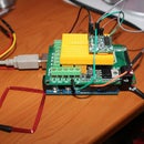
I decided to use a tilt ball switch to construct an inexpensive accelerometer (I bought mine from Adafruit.)
It’s really easy to use. We simply connect the longest out of the 2 pins on the GROUND and the other to the pin numbered A0 on the MicroView board. See the image attached.
With the Tilt Ball Switch connected on pin A0 we have to change the code in order to make it interact with the sensor: when the sensor is in the upper position and not moving, the value it returns is 0. When the value of the sensor is other than 0, it means that our dice is moving and the screen should display the random “rolling” images. Let’s see it in action:
In line 3 we’ll initialize the pin where the tilt sensor is connected. The program flow is really simple: the main loop will continually read the sensor’s value and if there is movement ( the value is not 0) the dice will continue “rolling”.
Step 4: Let’s Get Rolling


We are going to use a couple of hardware parts in order to free the Microview board dice from our computer and actually allow it to roll. What we need is 2 cell button batteries for the power supply and the proper cables for connecting them. Again, here’s an Instructable on how to create a battery pack.
The plus (+)/red cable of the battery pack has to be connected on the Vin pin on the Microview and the black cable to the GROUND, like the image attached.
Now we’re ready to go and just need to make sure the dice have the right feeling in your hand. I wanted to make a nice little 3D printed case and friend Nick was kind enough to design a plastic case for the MicroView and our parts.
Now you’re all ready to roll - literally! I really enjoyed playing with the MicroView board and the infinite options for creating that a small screen allows for. I hope you found this tutorial easy to follow, and your comments for any suggestions are much appreciated!


