

Introduction: Miniature Allianz Arena

This instructable was created in fulfillment of the project requirement of the Makecourse at the University of South Florida (www.makecourse.com). This instructable will walk you through how to make a miniature of Bayern Munich's Allianz Arena, or at least my attempt at making it.
Step 1: Required Supplies
3D Printed Objects:
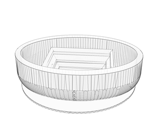
- Stadium
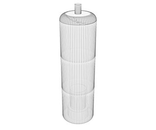
- Sign
- Post
Electrical Components:
- Arduino Uno R3 or greater
- Wire kit
- Breadboard
- 1000 uF capacitor or greater
- IR receiver
- Stepper motor
- Motor driver module
- IR remote, I used both the one supplied with the Arduino kit and an old Xbox 360 remote
- 60 Adafruit Neopixels
- 5V 10A DC power supply
Software:
- Arduino IDE
- CAD software, I used Autodesk Inventor
Other Supplies:
- Class supplied box/housing
- Acrylic paint and paint brushes
- Permatex Clear RTV Silicone Adhesive Sealant
- Velcro fasteners
- Drill with various sized drill bits
Step 2: 3D Design


I designed all the CAD parts for my project. The stadium, which is one part, is what took me the most time to design; I am not overly familiar with 3D design, and it took me a while to get the stands correct. The rotating sign was quite simple to design. It is two parts, the post and the sign, which I constrained together with a peg on the post and a hole in the sign.

Step 3: Control Circuit


The circuit for the design is very simple and easy to implement. The first photo shows the breadboard; everything there simply runs off the supplied voltage and ground from the Arduino. The only thing of note is the 4700 uF capacitor that I have for the Neopixel LEDs. 4700 is a bit overkill, Adafruit recommends using at least a 1000 uF capacitor to prevent a power surge from damaging any of the pixels. The second photo shows the Arduino, with the motor driver module going into pins 8-11, the IR receiver data line going into pin 3, and the Neopixel data line going into pin 5. Not pictured in this setup is the stepper motor which plugs right into the motor driver, and the DC power supply that plugs into the Arduino.
Step 4: Arduino IDE Code
The coding isn't too difficult to put together. The first section of the code includes the required libraries, defines what pins will be used, initializes some values, and creates the objects for each part to be controlled.
#include <Adafruit_Neopixel.h>
#include <avr/power.h>
#include <StepperAK.h>
#include <IRremote.h>
#define LEDPin 5 //LED strip pin 5
#define gearratio 64 //1:64 gear ratio for stepper motor
#define NUMPIXELS 60 // How many NeoPixels are attached to the Arduino
#define Pin1 8  //These set the pins for the Stepper Motor
#define Pin2 9
#define Pin3 10
#define Pin4 11
Adafruit_NeoPixel strip = Adafruit_NeoPixel(NUMPIXELS, LEDPin, NEO_GRB + NEO_KHZ800);//This creates the Neopixel object strip
int delayt = 500; // delay for half a second
const int stepsPerRevolution = 2048;//2048 steps turn the motor one revolution
Stepper myStepper(stepsPerRevolution, Pin1, Pin2, Pin3, Pin4);//Creates the Stepper Motor object
int RECV_PIN = 3; //IR Receiver connected to Pin 3
IRrecv irrecv(RECV_PIN); //Create a IR receiver object
decode_results results; //Create a decode_results object
The setup portion of the code simply enables the IR sensor, gears down the stepper motor, and initializes all the LEDs to an off state.
void setup() {
irrecv.enableIRIn(); //Enables the IR device
myStepper.setSpeed(0.15*gearratio);  //the motor appears to be geared down 1/64,
strip.begin();
strip.show(); // Initialize all pixels to 'off'
}
In the loop section, I used nested if statements for every time a signal was received by the IR sensor, it deciphers what that signal was, and does the corresponding operation to that signal. For each signal result if statement, I have a couple logical or operators, the first one is for the Arduino kit remote, the second and third ones are for the Xbox 360 remote. The reason I have two different signals for the 360 remote is because a different signal is put out if you hold the button down as opposed to simply pressing it. I have coded this into the program to accommodate for this signal discrepancy. The functions at the bottom are provided by Adafruit, and they can be easily modified depending on what you are looking to do with the LED strip.
void loop() {
	if (irrecv.decode(&results)) {//has a transmission been received?
		if (results.value == 2148529177 || results.value == 2148496409 || results.value == 16738455){  //If the "0" button or the "stop" button is pressed, the LEDs all turn off.
			colorWipe(strip.Color(0,0,0), 20);
      		}
		irrecv.resume(); // Receive the next value from the IR Sensor

  	}

 	if (irrecv.decode(&results)) {//has a transmission been received?
		if (results.value == 2148529164 || results.value == 2148496396 || results.value == 16753245){  //If the power button is pressed the LEDs all initialize to red        			colorWipe(strip.Color(255,0,0), 20);
		}
		irrecv.resume(); // Receive the next value from the IR Sensor

	}

  	if (irrecv.decode(&results)) {//has a transmission been received?
		if (results.value == 2148529171 || results.value == 2148496403 || results.value == 16724175){ //If the "1" Button or the "x" button is pressed do the following:        			colorWipe(strip.Color(0,0,255), 20);
		}
		irrecv.resume(); // Receive the next value from the IR Sensor
	}

	if (irrecv.decode(&results)) {
		if (results.value == 2148496422 || results.value == 2148529190 || results.value == 16718055){ //If the "2" or "y" Button is pressed do the following:
			colorWipe(strip.Color(255,255,255), 20);
		}
		irrecv.resume();
	}

	if (irrecv.decode(&results)) {
		if (results.value == 2148529185 || results.value == 2148496417 || results.value == 16743045) { //If the "3" button or "right arrow" is pressed do the following:        			theaterChaseRainbow(50);
		}
		irrecv.resume();
	}

	if (irrecv.decode(&results)) {
		if (results.value == 2148529184 || results.value == 2148496416 || results.value == 16716015) { //If the "4" button or "left arrow" button is pressed do the following:
			rainbow(50);
		}
		irrecv.resume();
	}
if (irrecv.decode(&results)) {
if (results.value == 2148496418 || results.value == 2148529186 || results.value == 16726215) { //If the "5" button or "Ok" is pressed do the following:
myStepper.step(stepsPerRevolution); //Rotates the stepper motor 1 revolution
myStepper.step(stepsPerRevolution);
}
irrecv.resume();
}
}
// Fill the dots one after the other with a color<br>void colorWipe(uint32_t c, uint8_t wait) { for(unit16_t I=0; I<strip.numPixels(); I++) {strip.setPixelColor(i, c);
strip.show();
delay(wait);
}
}
//Theatre-style crawling lights with rainbow effect
void theaterChaseRainbow(uint8_t wait) {
	for (int j=0; j < 256; j++) {     // cycle all 256 colors in the wheel
		for (int q=0; q < 3; q++) {
	        	for (int i=0; i < strip.numPixels(); i=i+3) {
				strip.setPixelColor(i+q, Wheel( (i+j) % 255));//turn every third pixel on
			}
			strip.show();
			delay(wait);
			for (int i=0; i < strip.numPixels(); i=i+3) {
				strip.setPixelColor(i+q, 0);        //turn every third pixel off
			}
		}
	}
}
// Input a value 0 to 255 to get a color value.
// The colours are a transition r - g - b - back to r.
uint32_t Wheel(byte WheelPos) {
	WheelPos = 255 - WheelPos;
	if(WheelPos < 85) {
		return strip.Color(255 - WheelPos * 3, 0, WheelPos * 3);
	} else if(WheelPos < 170) {
		WheelPos -= 85;
		return strip.Color(0, WheelPos * 3, 255 - WheelPos * 3);
	} else {
		WheelPos -= 170;
		return strip.Color(WheelPos * 3, 255 - WheelPos * 3, 0);
	}
}
void rainbow(uint8_t wait) {
	uint16_t i, j;
	for(j=0; j<256; j++) {
		for(i=0; i<strip.numPixels(); i++) {
strip.setPixelColor(i, Wheel((i+j) & 255);
}
strip.show();
delay(wait);
}
}

Step 5: Assembly and Completion

For the assembly, I used a silicone adhesive to bond most of the parts together. The stadium was bonded to the box, the sign and post were bonded together, and the I put just a bit of the silicone on the stepper motor and in the post so that they would be adhered together. Adhering the LEDs to the stadium was the trickiest part; this was largely due to the fact that the LEDs are in a weatherproof casing that prevents most adhesives/glues from working. The Permatex silicone adhesive I used was recommended by Adafruit for use on their Neopixels. I only painted the pieces slightly just to cause a contrast in their appearance and give the field the look of grass. I drilled all of the holes in the box so that the power cord, wires, and stepper motor could be put through. I also drilled a small hole near where the IR sensor to increase the chance of the IR signal reaching it. All of the electrical components are then placed inside of the box and secured with Velcro fasteners. Once everything has dried and is in place, the project is officially complete. At the end here, you can see a brief video of some of the functions in action.


