

Introduction: Mobility Assist Headlight


Walking with the assistance of a cane or walker, or using a wheelchair can be cumbersome as is, and poor lighting can make it worse. Adding lighting around the house or property works, but what about away from the house? Or even after turning out the lights on the way to bed? Sure, the person using the walker, cane, or wheelchair can also carry a flashlight, but how about a hands-free light? Here is a simple solution - a light mounted directly to the mobility device with a switch right where it needs to be!
If you have always wanted to start playing with electronics, this is a simple and low-cost project that will help you get your feet wet, while making life a little easier for someone with a disability!
The aim of this project is very simple: Take an off-the-shelf flashlight, and extend the on/off switch away from the flashlight so that both can be mounted to a mobility device in convenient locations!
For many of you, that explanation is enough! But a lot of detail will be provided in this Instructable for those who are not familiar with electronic circuits. If you aren't familiar with electronics, this is a simple first project! This Instructable is only long-winded to cover different concepts! It's not a sign that it's complicated!
Step 1: Parts and Tools Needed

Since different brands and types of flashlights vary, this Instructable will feature pictures of a specific type of light and switch, but will include general concepts that will help you build the project with parts of your choice! Just give it a try! You CAN do it!
The observant DIYer will notice some differences between the light on the walker and the light on the workbench, since photos were taken while building two of these lights. No worries; the concepts are the same!
Here are the parts and tools you will need:
Parts
Walker, cane, or wheelchair
Flashlight
Switch
Double-stranded wire
Velcro straps
Zip-ties or tape
Heat-shrink tubing (optional but helpful)
Tools
Screwdrivers
Pliers
Wire strippers
File or knife
Soldering iron and solder
Damp sponge for wiping soldering iron
Hot glue gun and glue (optional but helpful)
Multi-meter (optional but helpful)
Lighter for heat shrink tubing
Step 2: Choose a Light


First, choose the light that you want to mount to the device. Here are a few considerations:
Location: Where do you want the light to point? A flashlight with a light on the end can be mounted along the length of a cane or on the vertical bars of a walker with the light pointing at the ground. The benefit of this is that the light will shine around the feet, although a shadow may be cast by the cane or walker itself. The higher the light is mounted, the greater the area that is lit. Additionally, if used on a walker that has slightly slanted vertical bars, the light can shine down as well as a little forward. On a wheelchair, the vertical bar in front of one of the armrests may be a good option. Keep in mind that the footrests may block some of the light.
A flashlight with lights pointing sideways to the flashlight body may offer more options. If it is mounted on a walker's horizontal crossbar, the light can be positioned to shine forward, or rotated to point downward. On a cane, it will shine in a more forward direction. In either case, keep in mind that you can place something between the light and the device to tilt the light exactly where you want it.
Pictured above is a Bayco brand LED tasklight that has LEDs on both the end and the side. These types can be found at many department or hardware stores. They offer a very bright light, and the side LED array gives a nice wide angle of light, letting it illuminate the foot area as well as a little forward light. The light that is already attached to the walker in the pictures was a workplace gift, with some minor internal differences.
Second, consider the power source. Do you want something that is rechargeable, or that uses disposable batteries? There are pros and cons to both, such as cost while using, whether the light needs to be removed to change the batteries, etc.
A third consideration is the type of switch the light has. If the switch is easy to use and can be removed from the light, you can re-use the same switch in your project. If the switch is a part of the light body, such as is found on many flashlights with push buttons on the end, it may be easier to use a second switch of your choice.
Fourth, replacing the switch is easier if the light simply turns on and off. If it has other functions, such as flashing modes, different colors, or multiple lights (as the one used in this project), a little more effort will be needed... But not much! And you will be guided through it!
Also think about how you will attach the light. Double-sided Velcro (hook-and-loop) straps that attach to itself when wrapped around an object are great. These can be found in the craft section of your department store, or sometimes as cable-management wraps in the electronics section. Just make sure the straps are long enough to wrap around both the light and the bar it will be connected to.
Step 3: Choose a Switch and Wire


Choose a switch that will be convenient for the user to turn on and off. Some switches can be rather tough to turn on and off. Find something with enough of a body to the switch so that it can be mounted securely. There are many types available, as shown above. The simplest type of switch will have 2 contacts (wire connection points). Others may have 3, 4, or 6 contacts. This Instructable will not cover the use of a lighted switch, which usually has three contacts, and will require running an additional wire to the switch to make it work.
Switches with 3 contacts, or 6 contacts in 2 rows of 3 can be used by connecting one of the wires to the center (common) contact, and the other wire to one of the end contacts (if using a switch with 2 rows of 3 contacts, use the contacts on one 3-contact row). One switch position will be on, the opposite direction will be off (see pictures above)
Avoid using momentary switches, as this will require the user to press and hold the switch to keep the light on.
A good type of switch to use is an automotive rocker switch, which can be found at an auto-parts store, or the automotive section of a department store. Although they are intended for 12-Volt applications, they will work just fine for this project, which will most likely be powered by 6 volts or less, depending on your light.
If you have a multimeter, you can use it to find which contacts are connected for a given switch position. This will be covered in a later step.
Think ahead about how you want to mount the switch: Glue, tape, zip-ties, etc.
For the wire, it is easiest to use double-stranded wire, such as audio speaker wire. One of the lights pictured uses audio wire, while the other uses wire cut from an wall plug. The gauge doesn't matter much since the wire length will not be drastically long, and since only low voltage is being used. Use wire long enough to route from the light to the placement of the switch. For a walker or wheelchair that folds, keep in mind that you will need to run the wire so that it does not get pulled or pinched when the walker/wheelchair is folded and unfolded.
Picture 2 credit: www.cubisteffects.com/
Step 4: Disassemble Flashlight


Now the fun part! It's not yours til you take it apart! Before prying your light apart, check the outside of the case carefully for screws, including under sticker labels. Remove any screws you find.
Every flashlight will be different, so here is how the light pictured above came apart: This light had no screws holding it together, only plastic clips formed into the case that pop apart. Take off the battery cover, take out the batteries, and insert a screwdriver to use as a pry bar. Hold the light at the battery compartment end, and lift the handle of the screwdriver gently but firmly. You will hear a pop, and the case will slightly separate at the battery compartment. Use a finger if needed to pry more. This light had 3 sets of clips, so it popped twice more before coming apart.
Once the case is in 2 pieces, the rubberized cover for the on/off switch will simply fall out. This light - as well as the other free light - had a circuit board to which the LEDs, switch, and battery springs were connected. Check the board carefully for mounting screws, and remove if there are any. This light happened to only be secured with glue (arrows on 5th picture). Use a small screwdriver or knife to gently scrape away the glue, then lift the circuit board out. The clear lens and light shroud at the end simply lifted out of the case.
If your switch is not mounted directly to a circuit board, then it probably has wires connected directly to it. Leave these intact until you determine what wires are what.
Step 5: Determine How the Switch Works


If your flashlight has multiple lights (Front, side, top, bottom, etc. NOT meaning multiple LEDs to make up an array), then the most difficult part of this build will be to figure out which switch connections go to what part of the light. If your light only has one function (on and off) then your switch will only have 2 terminals, and you can completely skip steps 5 and 6, and go to step 7!
If your light is like the one pictured above, with multiple functions and a switch soldered to a circuit board, then there are 2 ways you can wire up your own switch. Either way, you will need to know where to attach the wires for your new switch. Here are a few ways to figure it out:
First, you need to know the sequence of the various light functions. This could have been done before disassembly, but just in case anything was bumped, you need to know what function the switch is in now. Lay the circuit board back in the body, and insert the batteries. Now, cycle through the switch functions, and write down the order of the light operation (pictures 1 throug 4).
In this case the light has 3 different on functions, plus off. Cycle the switch to the "OFF" function. Now take a close look at the switch. This switch has 4 pins: One will be connected to the battery source, and each of the other 3 will provide power for one of the functions. It can be helpful to draw a sketch of the switch and label the pins so you remember it later.
The first method of testing is the easiest, and is safe for testing a flashlight. With the batteries still in (and the switch still off), take a piece of wire with both ends stripped and touch it to 2 different terminal. Check every possibility (e.g. 1 and 2, 1 and 3, 1 and 4, 2 and 3, 2 and 4, and 3 and 4) until something lights up, then write down the 2 pin numbers and which function that combination turned on. Do this until you have the 3 on functions figured out.
NEVER use this method on high voltage or high current circuits.
If this is the method you used, you can skip Step 6 and go to Step 7. Step 6 shows 3 different ways to use a multimeter to figure out the pin connections.
Step 6: Using the Multimeter


Identify by Voltage
The first multimeter method will be to identify the pins by voltage. This is the only test that will be done with the multimeter while the batteries are still in. All 3 methods will use the red probe connected to the multimeter's voltage, low current, and resistance port, and the black probe connected to the ground (COM) port.
Each AAA battery in this light provides about 1.5 Volts, for a combined voltage of about 6V. Turn the multimeter selection switch to the DC Voltage function ("V" with a straight line above it, shown in first picture). If your multimeter does not have auto-ranging, then turn the dial to the first DCV setting higher than 6 Volts (usually 20). With the light's switch still in the off position, place the black probe onto the the battery spring closest to the board that touches the negative side of a battery. Check the connection by placing the red probe on the spring closest to the board that touches a positive battery terminal. The meter should read around 6V. Keep the black probe where it is, and touch the red probe to each of the pins on the switch. One of them will also read a voltage that is greater than zero, while the rest of them will read zero. The result may not be 6V due to other components in the circuit. Whichever pin is greater than 0V will be the pin that is connected to the battery supply. This will be one of the pins that a wire is soldered to. If the probes were reversed so that the black was connected to the positive side of the circuit, the only difference is that the voltage will be displayed as a negative value.
Now press the light's switch once to turn the light on in its first function. With the red probe, test the other switch pins. One of them will show a positive voltage, in addition to pin connected to the batteries. Write down the battery pin, the pin that is now showing voltage, and which function of the light is on.
Press the switch to the next function, and probe the remaining pins to identify which one is what. Write down the pins and the function, and repeat until all the functions are identified.
Identify by Audible Conductivity Function
Remove the flashlight batteries for this step.
Some multimeters have a function that makes an audible tone when the probes are both touching points that are electrically connected together. This is the ideal way to test the switch. Place the meter's dial to the symbol that has the multiple curved lines portraying a sound wave (picture 2). With the light's swicth in the off position, probe 2 of the switch's pins at a time, going through all the combinations (1 and 2, 1 and 3, 1 and 4, 2 and 3, 2 and 4, and 3 and 4). It does not matter which color probe goes to which pin. No tone should be produced in this switch position. Press the light switch to the first function, and probe the pins the same way until the meter produces a tone. Some meters may also display a message such as "SHORT," as in picture 2. Write down the function, and the pair of pins that produced the result. Press the light's switch to the next function and do the same. Repeat until all functions are identified.
Identify by Resistance
With the batteries still removed, turn the multimeter dial to the ohm symbol (Greek letter omega). Never turn the multimeter dial to the resistance function while the probes are connected to a circuit which has power. That will destroy the multimeter. With the light's switch in the off position, probe all the switch pin combinations as in the last method. Again, probe color does not matter. The number "1" with no zeros or other numbers should be displayed on the meter for all combinations, which indicates infinite resistance (i.e., no connection). Press the light's switch to the first function, and probe all the pin combinations. All but one combination will show a "1" on the display, and one combination will show a very small number (picture 4). Write down the combination with the non-"1" result and the corresponding function. Repeat through all the light functions.
Whichever method you use, proceed to the next step once you have all the functions identified as in the last picture.
Step 7: Remove Extra Components


Since this flashlight has a light on the end which won't be used, take it off and throw it in your parts bin for another project!
The light pictured above had the end light mounted to a second circuit board which was perpendicular to the main board. Remove any glue you find holding the 2 boars together. Most of the connection on the board above was made by the soldered joints, shown with arrows above.
If you have never soldered or de-soldered, the concept is simple, but does require practice to do well. Avoid breathing fumes from molten solder, as most solder contains lead.
Whether soldering or de-soldering, it is always best to "tin the tip" of the soldering iron before starting. This will make your soldering job go more smoothly and prolong the life of the iron tip. Old or used solder will contain impurities that will concentrate heat onto small areas of the iron tip, which will cause that area to burn out and become unusable. Impurities will also make it more difficult to get the solder to adhere where you want it to. To tin the tip, simply turn on your soldering iron and let it heat up. Unwind a few inches of new solder from your roll, and press the end of the solder wire onto the tip, letting it melt onto the tip. Only use enough to make the tip a shiny silver. If the molten solder begins to form a droplet on the tip, you are using too much. Excess solder can be removed by wiping the hot tip onto a damp sponge, or by pressing the tip into a brass mesh tip cleaner.
For de-soldering the end light board, you do not need to add any new solder. it will be easiest if you have a set of "helping hands" to clamp the main board into, but a pair of vice grips gently clamped to the main board will work as well. Simply touch the hot tip of the iron to one of the solder joins. If your iron is hot enough, it should melt quickly. Use a pair of pliers or one of the screwdrivers to press the perpendicular board away from the main board on that side, while keeping the iron tip against the solder to keep it molten. Solder cools and solidifies quickly. You may need to work on both sides alternately a little at a time to remove the board.
The end light board, reflective shroud, and clear lens can be saved for other projects.
Step 8: Remove Switch


The switch could be left on the flashlight, with the new switch's wires soldered to the terminals in place... but why miss out on another extra part for your parts bin?
Depending on what type of switch your light has, removing it can be a little more tricky. If your switch is connected to the rest of the circuit by wires, you get the easy way out! Simply cut the wires and strip the ends, then go on to Step 9!
If your switch is soldered directly to a circuit board, it will be one of two types: through-hole, or surface mount. A through-hole component has longer leads that will pass through holes drilled in the circuit board, and will be soldered on the opposite side as the component. A surface-mount component will be soldered on the same side as the component itself, down where the part touches the circuit board. In either case, the solder will need to be reheated to remove the part. It is usually a good idea to hold the part being desoldered with a pair of pliers. Most components, especially switches, contain plastic which the soldering iron can easily melt and ruin. Holding the part with pliers, or using a heat-sink clip, gives the heat another avenue to escape, giving you a few more seconds to complete the desoldering.
Surface-mount parts can be easier to desolder, as the solder forms the only connection to the board. Heat the solder connection with the iron while pulling gently on the part with the pliers, or gently lifting or pushing with a screwdriver.
For a through-hole part (as in the example), grip the part gently with pliers, then turn the board over. Heat the solder holding the ends of the pins while pulling on the part with the pliers (or prying gently with a screwdriver). If the leads are longer, you may need to work each pin alternately a little at a time until the part is removed. If the pins become stuck at the very end, you can push the tip of the soldering iron into the hole slightly to melt the last little bit of solder.
Always try to limit the length of time that the part is being heated to avoid ruining the part.
Desoldering braid (the string of copper mesh coming out of the white package in picture 2) can be very helpful. To use it, pull a few inches of the braid out of the packaging, grasp two points of the braid about an inch apart and gently push together slightly to spread the braid. Place the spread part of the braid on the joint to be desoldered, then push the braid into the solder joint with the heated tip of your iron. The iron will heat up the solder through the braid, and the copper of the braid will draw the molten solder into itself. When the solder liquefies, sweep the desolder braid and the soldering iron together sideways away from the joint.
CAUTION: Don't forget that the desolder braid will get hot along with the tip! Hold the braid several inches from where the iron touches it, or use a pair of pliers so you don't burn yourself!
Molten solder can also (rarely) be thrown from the board if the part releases suddenly. Watch your eyes!
Step 9: Solder Wire to New Switch


Now that the original switch is removed, it is time to add the switch you chose. If using double-stranded wire, a few inches of the end that will go to the switch will need to be separated so that heat shrink tubing can be added (picture 2). Strip enough coating off the ends of the wires to ensure a good connection to the switch terminals. If the terminals have a small hole in them, the bare wire can be inserted through the hole and then twisted onto itself before soldering. If the terminals do not have holes, you will want to strip enough coating to wrap the wire around the terminal and then twist onto itself. Good mechanical connection first; good solder connection second.
Take 2 pieces of heat shrink, and cut one piece in half. Take the larger piece of heat shrink and slide it over both of the separated wires. This will become the final outer coating. Now place one half-piece of heat shrink over each of the separated ends of wire (pictures 3 and 4). Now connect each wire to one terminal. Reference the pictures in Step 3 if your switch has more that 2 terminals.
Soldering the wires to the switch is easier than desoldering. Tin the tip of the soldering iron again and wipe off the excess solder. Touch the soldering iron to both the wire and switch terminal at the point where you wrapped the wire around. Keep the iron in contact with the parts while touching the end of the solder to the PARTS (not the iron). Once the parts are hot enough, the solder will melt onto the parts. Add enough solder so that a smooth covering of solder coats the wire and the terminal immediately around the wire. Again, you don't want a droplet of solder forming - just enough to fasten the parts together.
Important: The whole process should take about 10 seconds. If the soldering iron is in contact with the part longer than that, the heat can begin to melt the plastic and/or internal parts of the switch, causing damage. You want to heat the parts to be soldered, and let the solder melt onto the parts. Do not melt the solder onto the iron and then try to wipe the solder onto the parts. This can create a bad solder connection called a "cold solder joint."
Now slide the half-pieces of heat shrink tubing onto the terminals to protect the solder joints. Hold a lighter below the heat shrink to heat it (without letting the flame touch the tubing). Once each terminal is covered, slide the full piece of heat shrink over both of the other pieces of heat shrink and heat to reinforce the whole connection. You may have to bend a terminal to accomplish this (pictures 8 and 9).
Step 10: Solder Wire to Light


The new wire now has to get into the light from the outside. If the old switch or other part that you removed left a hole in the case, you can route the new wire through that hole. Worst case, you may have to drill a hole in the flashlight body to run the new wire in. Run the new wire through the case where you can. If the hole the wire passes through is about the same size as the wire, tie a knot in the wire on the inside of the case a few inches from the end. This will prevent the wire from being yanked out if it gets caught on something. In the flashlight in the pictures, the lens on the end was removed, allowing the wire to enter from the end. If using the knot method, make sure that a knot in the wire will not prevent the flashlight body from being closed.
Separate and strip the other end of wire to be connected to the circuit board. The stripped end can be much shorter since it does not need to be wrapped around anything. Reference your diagram from figuring out the switch, and solder one wire to each of the appropriate points on the board.
If the switch that you removed was a through-hole switch, you will need to push the wire through the holes from the side that the switch was on, and solder on the opposite side. In this case, if the hole is clear, simply insert the wire, turn the board over, and hold the iron to mostly the wire with just the tip in contact with the contact on the board. Add solder to the heated wire and allow it to flow onto the board contact. Only add a small amount of solder. If excess solder runs onto the board it can contact another part of the circuit causing a short circuit. If the holes are covered with solidified solder, twist the end of the wire to create a tight bunch. Gently press the wire end to the solder while heating the solder from the other side of the board. Once the solder melts, you will be able to press the wire through the hole. Press the wire all the way through before removing the iron. Often, this will produce a good enough connection as the solder re-solidifies, without having to add more solder. If the wire does not wiggle around in the re-solidified solder, then the connection should be good.
If the switch was a surface-mount, the new wires will be soldered to the same side that the switch was on. Make sure the stripped ends of wire are not so long that they will contact an unintended part of the board. Hold the end of the wire to the appropriate contact point, touch the iron tip to the wire, then add solder to the heated wire.
If the original switch was connected to the rest of the circuit with wires, you simply need to strip the ends of the wires you cut, place heat shrink tubing over the wires, and twist each of the old wires to an end of the new wire. Heat the twisted junctions with the iron, and add solder to the wire. Cover the connection with heat shrink when finished.
Step 11: Test

At this point, the circuit should work! Insert the batteries and flip the switch! If the circuit does not light, start by checking the orientation of the batteries (always start with the simple). Next, check to make sure that you connected the wires to the right points. Also check to make sure that excess solder is not bridging other parts of the circuit. If it is, you may need to desolder the bad joint and re-solder. Still not working? Tug very gently on the wires while the switch is on. If the light flickers on on off, then you probably have a bad solder joint. Figure out which one it is by tugging different spots, then fix it by desoldering and re-soldering that connection. Still nothing? Check to make sure that you did not damage the switch with the heat of the iron. Take a little piece of bare wire and touch it to both of the terminals of the switch to create a temporary bypass. If you did such a good job of heat-shrinking that you can't get to the terminals, touch the ends of the wire to the contact points on the board. If the light goes on by using the short jumper wire, then the problem is in the new wire or the switch.
Step 12: Secure Internal Parts and Wire, Test Again


If everything went well and the light is working, it is time to secure the new wiring to make the whole light more rugged. You don't want all that work being ruined by having the wire yanked out. Tying a knot as in Step 10 is the best way, but sometimes that just can't be done with the device being modified.
In this case, hot glue is a very useful tool. Lay the wire against the circuit board or a free area of the flashlight body. Leave just a little bit of slack where the wire connects to the board so that the connection is not strained. Apply hot glue liberally, so long as it does not prevent the case from closing. you can also tidy up other openings such as by gluing the rubber switch cover back into the body.
If you find that the case needs some more altering to allow the wire to exit, a small file can be used to create a groove for the wire (arrow on picture 3).
Test the light again to make sure you did not disturb any of the connections!
Step 13: Reassemble, Test Again

Everything work? Great! Reassemble the flashlight body in the reverse order of the disassembly. If any small plastic clips broke, use tape, hot glue, or zip-ties to hold everything together... AFTER you checked it a final time, of course! Hot glue can also be used to fill in any large open areas - such as the end - to make the light more weather-resistant.
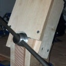
Step 14: Mount Light, Wire, and Switch


Now that the light is back together, mount it to the walker, cane, or wheelchair! Double-sided Velcro (hook-and-loop) straps work great, and allow for easily changing the batteries. Zip ties and electrical tape are great for securing the wire to the frame. Be sure to let a little slack in the wire near any pivoting or folding points so that the wire does not get broken. If the wire connection to the switch terminals is stiff and strong enough, securing the wire just below the switch may be enough to mount the switch. Tape or zip ties can also be used around the switch body.
Of course, after completing this project, you are now more than qualified to design and build your own custom mount for the light!
Step 15: Use!


Finished! Not only have you made a useful item that will make getting around a little safer and more convenient for someone, but now you have a few more skills to put to good use in other projects as well!

Participated in the
Make It Glow! Contest


