

Introduction: Modify Sony VGP-SP2 Speakers for Non-Docking Station Use

Years ago I bought a Sony Vaio laptop which came with a docking station and some nice speakers. I recently donated the laptop, but kept the speakers in hopes of using them with my newer desktop computer. The problem is that the speakers were designed to work only with that docking station. They connected to it via two normal speaker connections, an audio jack, and a USB plug. Further research revealed that the speakers do not have their own amplifier, but used one contained in the docking station. I didn't find much on the internet on how to convert these speakers, but it didn't seem like it would be too hard to do.
This instructable details what I did to hack the speakers, as well as some of the lessons learned. This was the first electronics project I've done in many years, so I'm sure there are additional things I could have done better. However, I can say that it did work, and the speakers sound great when playing music and games.
Design Thoughts
The basic idea is to put a small amplifier board inside one of the speakers, wire the existing volume knob to it, and power the board with the USB cable. The amplifier I chose was this one from Adafruit. It is small, cheap, runs on 5V, and has stereo support. One of the speakers has a space where an IR module sits, and this amplifier can easily replace that.
The volume knob is a bit of a problem. Since it is located in the other speaker from where the IR module is, a wire will be needed to connect to the amplifier. For me this is not a big deal since the speakers will sit on either side of my monitor. Also, the audio wire from the volume speaker already has to go to the other one, so what's one more wire? Of course, this also means the audio cable from the computer has to go to the volume speaker. I could just not have a volume knob, but I'm choosing functionality over aesthetics.
This is an afterthought, but my first iteration of this project I just soldered wires directly to the amplifier board and audio potentiometer. Turns out the connections were not great, and there was static and loss of one speaker when I went to use them. I ended up using crimp connectors that slide onto header pins, and securing everything with heat shrink tubing. I knew I should have done this in the first place, but I was lazy. Lesson learned.
Step 1: Parts and Tools
Parts
- Pair of Sony Vaio VGP SP-2 speakers
- 1/8" (3.5mm) male stereo audio plug and cable, but with free wires on the end
- 50k dual audio potentiometer
- Adafruit Stereo 3.7W Class D Audio Amplifier - MAX98306 (available here)
- Solder
- Heat shrink tubing
- Crimp connectors for standard header pins (Ex: from Sparkfun)
Tools
- Soldering tools - iron, helping hands, desolding braid, etc...
- Wire strippers and cutters
- Heat gun
- Phillips screwdrivers
- Utility knife or box cutter
- Regular and needle nose pliers
- Hack saw with metal blade
- Metal file
Nothing too special required for this project, except the audio pot and amplifier. Any audio amplifier could work as long as it is small and can drive 15W 8 ohm speakers. The Adafruit amp is the one I found at a low price.
Step 2: Disassemble the Speakers

First order of business, take everything apart. There will be a lot of screws, so be sure to keep them grouped and contained. Even though I was careful to do this with a magnetic dish, I still lost a few by the time I was done.
- Remove the two magnetic collars from the speaker wires.
- Remove the front mesh from each speaker.
- The mesh is attached via a number of plastic pegs inside deep wells within the housing.
- Drive a screwdriver blade or other pry tool between the mesh and housing, and rotate to make a small gap.
- Work your way around the perimeter until you can use the screwdriver to lever up the sections with longer pegs.
- Remove the ten screws set in the wells
- Draw the point of the utility knife all the way around the seam between the front and back halves of the housing. There is an adhesive strips between them that you need to break.
- Use the same technique as in Step 1 to separate the halves. This should not be too difficult.
- Pull off the four adhesive feet from the bottom of each speaker, then remove the four screws beneath them.
- Remove the bottom section.
- Using the utility knife, carefully remove all wires from the glue points, undo any tape, etc... Sony really wanted to make sure nothing in here moved around.
- On the speaker with the volume knob:
- Pull the plastic volume knob off
- Unscrew the hex nut on the outside of the knob
- You can now remove the potentiometer from inside. You may need to pry it off.
- There is a plastic disc inside that holds the potentiometer in place. Pry that off as well.
- Cut the three wires on the potentiometer.
- On the speaker without the volume knob:
- Undo the two screws on the little plastic drawer at the bottom of the speaker.
- Remove the IR module. You may need to pry it out.
- Cut the USB wires from the IR module.
When you are done, you should have a pile of stuff that looks like the picture.
Step 3: Prepare the Volume Potentiometer


Depending on the potentiometer you buy, you may need to reshape its post to fit the volume knob. The first photo shows the one I had, which is too long and round. There is also a small tab on the pot that fits into that plastic disc (second photo). This keeps the pot from turning with the knob when installed. You will also need to shape this tab and/or hole.
- Use a hacksaw or rotary tool to cut the post to length.
- Use a file or rotary too to flatten one side. Be careful to make sure it is flat or the volume knob will not slide on all the way.
- It is probably easier to use a file to shape the tab to fit in the disc's hole. You could use a utility knife to shape the hole, but the plastic is hard and difficult to tweak in such a small size.
The third photo shows the results.
Step 4: Prepare the Volume Cables
The original cable from the volume knob ended in a 2.5mm plug, which is too small for computer audio jacks, so it needs to be replaced. We also need a second audio cable to hook the volume pot up to our amplifier in the other speaker.
Prepare the linking cable
- Cut off the 2.5mm plug from the original speaker volume cable, then strip the outer insulation to expose the inner three wires.
- One one end, divide the unshielded ground wires into two sections. Twist each section to secure the the bundle.
- Solder crimp connectors onto these two ground sections as well as the single one at the other end.
- On both ends, strip the insulated wires, then solder on the crimp connectors.
- Add heat shrink tubing around all wires to secure the connections to the crimp connectors. If the tubing will hide the wires' colors, make sure you note which ends correspond to each other. You may want to add a small flag on the tubing.
Prepare the audio cable
- If needed, strip the end of the 3.5mm audio cable to expose the three inner wires.
- Strip these wires and solder on crimp connectors.
- Add heat shrink tubing around each crimp connection to secure them.
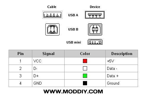
- Use a continuity checker to find out which wire corresponds to each part of the audio plug (reference):
- Ground is the outer section, should be unshielded
- Right is the middle section
- Left is the inner section
- Make note of which wire is which. If the heat shrink tubing hides the wires' colors, add a small flag on the tubing.
Step 5: Assemble and Install the Volume Control

The potentiometer should have six legs in a 2x3 configuration (see photo). The two pins at one end will be ground, and the two pins at the other end are for audio input. The two pins in the middle are the audio output. The end you choose to be the audio input will correspond to max volume. If you choose wrong, it just means the volume markings on the speaker will be reversed.
At the top of this page is a diagram that shows the connections on the potentiometer.
- Solder a small jumper wire between the insides of two pins you chose to be the ground. Going on the inside is best because the wire will not interfere with the slip on connections.
- With the audio cable, attach the ground connection to a ground pin, and the other two to each of the pins at the audio input end of the potentiometer.
- With the link cable use the end with the single ground. Attach the ground connection to the other ground pin, and the other two to each of the middle potentiometer pins.
- Put the plastic disc on the potentiometer, insert the assembly into the speaker so the bumps line up, then secure it in place by screwing on the hex nut.
- Put the volume knob on the post.
NOTE: Make note of which wires on the link cable are for the left and right audio channels.
Step 6: Assemble the Amplifier

Here is the official Adafruit page for doing this. Basically you just solder on some header pins and terminal blocks, but here are a few notes:
- I replaced the straight header pins on the inputs with right angle ones (see photograph). I figured this would be better for directing the wires when installing the amp into the speaker. It worked, but routing the wires might be easier if I had just used the straight pins.
- I put the gain jumper on the 18 dB setting, but you can choose whatever you want. I figured I had a volume knob to control things, so the maximum amplification should be fine. You can always play around with it once everything is connected, but not closed up.
You are also going to need to modify the USB cable to power the amplifier:
- Strip the USB cable to expose the inner wires. There should be five, but we only care about the power and ground.
- According to the USB pinout, the red wire should correspond to the 5V pin on the outside right of the USB connector, and the black to the ground pin on the outside left. You may want to confirm this with a continuity check.
- Remove the ends of the other three wires since they are not needed.
- Strip the ends of the 5V and ground wires and solder on crimp connectors.
Add heat shrink tubing around the wires to secure the crimp connections.
You can now connect the USB and linking cables to the amplifier. The result looks like the photograph.
Step 7: Install the Amplifier

- Place the amplifier in the IR module space. Take the wires for that speaker and measure how much you need to reach the amplifier's terminal block. Cut off the excess. You should only need 6" or so.
- Measure out the speaker wire from the other speaker so it is about as long as the linking cable. Cut off the excess.
- Strip and separate the ends of both sets of speaker wires. Insert and secure them in the amplifier's terminal blocks.
- You will need to cut some holes in the sides of the IR tray for all our wires:
- Put the amplifier upside down in the tray and measure how wide the holes need to be on each side of the tray. The holes will be just in front of the screw brackets.
- Use a knife or small saw to cut the hole, and pliers to pull the plastic out. The hole will need to be a bit deep (see photograph)
- Put the amplifier upside down in the tray, make sure the wires sit in the holes nicely, then install the tray in the speaker and secure both screws.
Step 8: Test Everything
Now is a good time to make sure everything works before putting 20+ screws back. I didn't do this on my first iteration, and had to disassemble everything to fix some bad wiring.
- Make sure the volume control is turned down
- Plug the audio USB cables to a computer and fire up some music
- Adjust the volume and make sure it affects both speakers equally
- Move and jostle the speakers a bit, or wiggle the crimp connections a little. There should be no static or audio loss from either speaker.
If you get uneven sound, static, or audio loss, go back and check each crimp connection to make sure it is secure. As I have mentioned in the intro, I had a bunch of issues on my first iteration or two because I was lazy and soldered bad connections. Once I went with the crimp connectors, all was well. Hopefully you will not have to go through that.
Step 9: Close Everything Up

Before closing up, we need to make some new access holes for the new wires. In each speaker, we need one hole for the speaker wire and two for cables (see photograph). For both speakers:
- On the inside bottom edge, use a utility knife and pliers to expand the existing cable hole until it is big enough for two audio cables to sit in. Also add an additional hole big enough for the speaker wire to pass through.
- On the outside bottom edge, expand the two existing holes if needed to a single audio cable and the speaker cable. Add an additional hole between them for another audio cable.
Time to put everything together! For each speaker:
- Route both audio (or USB) cables through the double inner hole and out each of the two outer holes. You can use tape to hold them in place, but the friction should be enough. Make sure to avoid sharp kinks.
- Route the audio cable though the inner hole and out the outer hole. Again, you can tape if you want.
- Line the front part of the speaker up and carefully push it against the back. Make sure all the cables stay in the holes.
- Fasten the front part of the speaker with the ten screws you removed earlier.
- But the bottom of the speaker on, being careful to line the cables up with the outer holes. Secure with four screws and put the sticky feet back on.
- Install the front mesh of each speaker by pushing the posts into the holes. Apply even pressure.
I didn't put the magnetic collars back on the speaker wires. One is now hidden inside a speaker, and I figure things are probably good enough without them. I also didn't go to the lengths of securing the wires inside the speakers like Sony did, so don't go swinging them around by the wires.


