

Introduction: Motion Activated Christmas Lights


In this Instructable, I will show you how to make your Christmas lights turn on when there is someone in the room using an Arduino, relay module and a PIR motion sensor.
I made this because I wanted the lights on my miniature Christmas tree to turn on to greet someone when they opened the door.
Step 1: Parts Required


For this project you will need:
Essentials
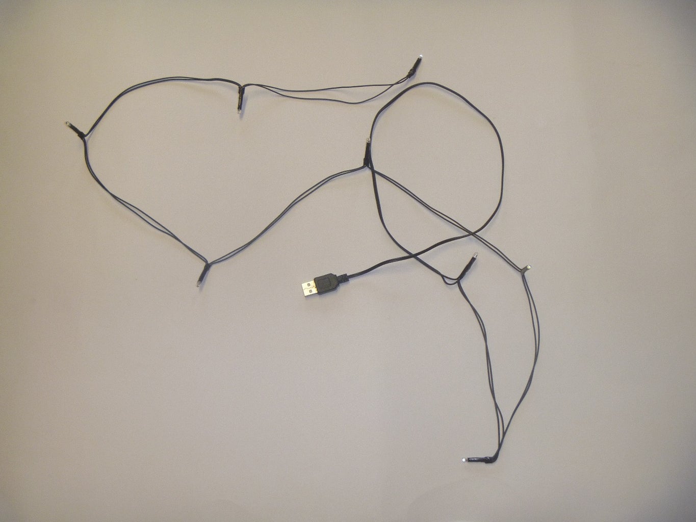
- Some fairy lights
- Mine are a string of 8 LED, powered by USB
- A PIR sensor (this sort of one)
- An Arduino
- A relay switch
- Wires: use either
- Male to male jumper wires (link)
- You should use this if you're planning on disassembling your project after Christmas
- Or single core or multi core wire with the ends stripped off
Use this if you're not going to disassemble your project after Christmas and are going to solder your components together
- Male to male jumper wires (link)
Optional Extras
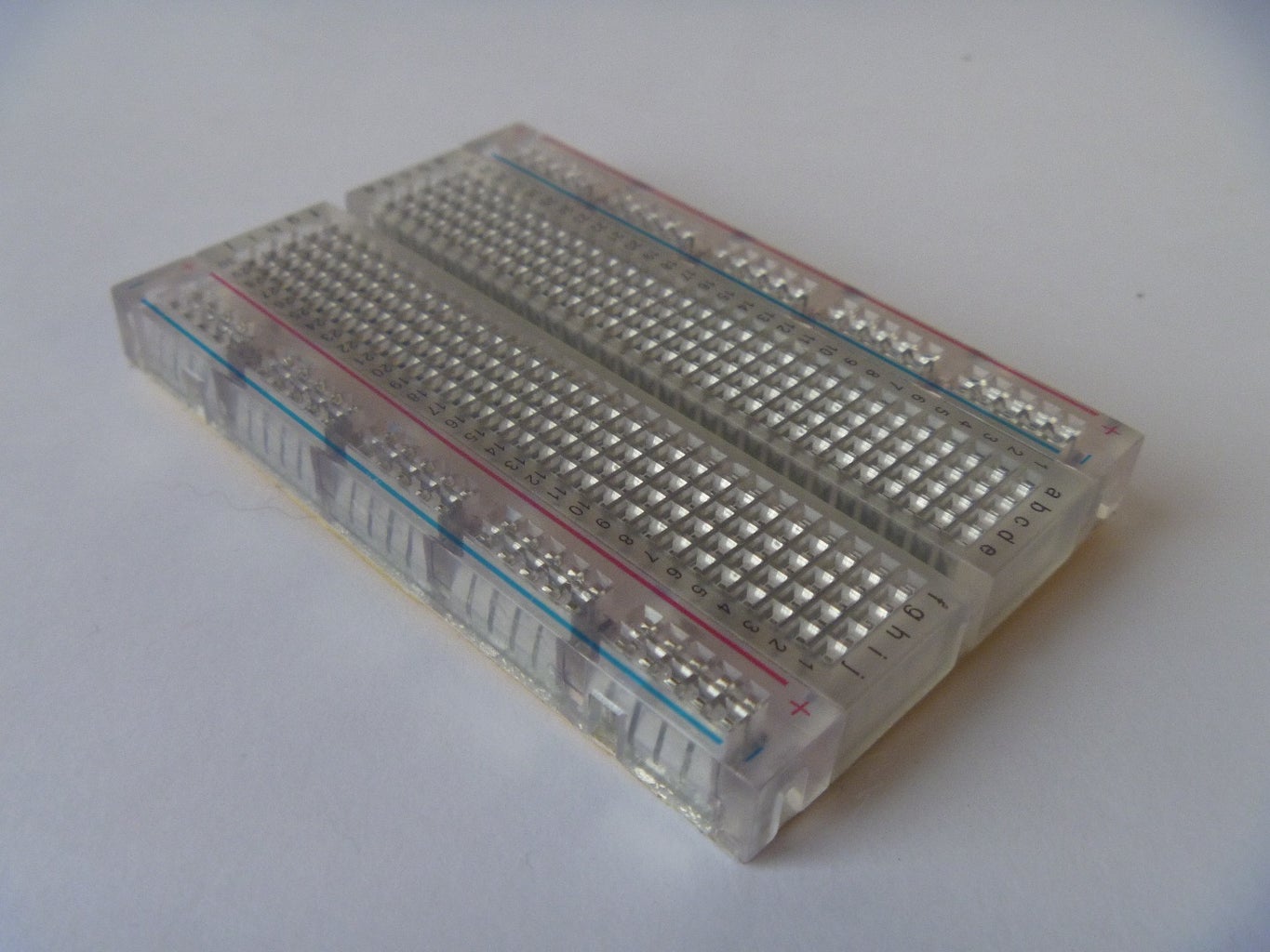
- A breadboard
- Male to female jumper wires - this makes the connection to the PIR sensor easier
- A USB breakout board (I used this as my fairy lights were USB powered)
Step 2: Using the PIR Motion Sensor


PIR stands for passive infrared - it detects motion by changes in the changes in amount of infrared radiation that falls it. To find out more, look at this Wikipedia article or an introduction from Adafruit.
First connect the PIR sensor to the Arduino as shown in the diagram above using the male to female jumper wires and upload the code below.
If you are unfamiliar with Arduino, have a look at Getting Started with Arduino. Have a look at this Instructable if you're struggling with getting the PIR sensor working.
If you've got an Arduino with an LED connected to pin 13 (e.g. Arduino Uno) you should notice that the LED lights up each time you move. If you open the serial monitor (see screenshot with arrow on how open the serial monitor), you will get told about when motion is detected. Remember, it only tells you when the last motion finished when the next one starts (see the last block of code).
Attachments

Step 3: Relays
We will control the lights with a relay module. Using a relay makes it possible to control things which are not directly powered by the Arduino. An explanation on how they work can be found here.
Connecting the controlling wires
If you've got a relay like in the photo, connect the relay to the Arduino using female to male jumper wires:
- => GND
+ => 5V
S => Pin 13
With just relays and not the module you only need to connect up Pin 13 and ground. Beware that some larger relays draw a lot of current so could damage your Arduino. You'd need to connect it up to a transistor if this was the case.
You can test if your relay is working by using the example sketch Blink or by touching the wire from the S pin to 5V. You probably have a mechanical relay, you should hear a click every second if you're using the Blink sketch.
Connecting to the power you want to switch
Relay connections:
C - The common pin. This is where the power gets fed in - i.e. your power supply. I just use the 5V Arduino pin for my USB lights as 5V is standard USB voltage.
NO - Normally Open. When current flows through the switching mechanism, the switch closes and current can flow through the non-arduino loop. This is the other side of the switch so is where power gets fed out.
Step 4: Connecting the Lights


Connect the light power input to the common pin.
Connect the lights to Normally Open (NO).
Refer to the diagrams for help but beware that your relay module may have a different pinout. As I said, I used USB lights as they were powered by 5V so can be powered by the Arduino. I made this USB breakout board so I did't have to cut the wires and I can still power the lights from my laptop if I want to.
Step 5: Finish & Troubleshooting

With everything connected the lights should turn on when you move in front of the sensor. If the lights turn off when you wave then you may have the lights connected to normally close, not normally open as they should be.
If you want the lights to stay on longer than 5 seconds after detecting motion change the value of pause in line 25 of the code.
Any questions or suggestions welcome in the comments.
Step 6: Developments & Ideas From the Comments

Future Possibilities
In time for next Christmas I'm going to modify and upload the code to an ATtiny85 (an 8 pin Arduino programmable chip). I will then be able to put it on a small PCB so will be much easier to hide away from sight and will also have no bright status lights and use less power.
I'll be posting various other developments on my blog and will be putting some more on this page as they come...
Ideas from the comment
Suggestions welcome.


