

Introduction: Motion Activated Lamp


It's night and you need to go to the bathroom but you don't want to turn on the lights, yet stumbling in the dark isn't quite pleasant either, then what do you do? I built this led cube, which turns on when you move it - for example grab it in your hand - and turns off after a certain amount of time.
I'm not an expert in electronics nor am I a very good at woodworking. So building this lamp doesn't require any special know-how, yet some basic knowledge in electronics and soldering might come handy in this project.
Parts that I used:
- Arduino Nano
- GY-521 MPU-6050 Gyroscope/Accelerometer
- 24x blue leds
- 8x 150ohm resistors
- 3x NPN transistors
- 2x AA-battery holder
- Some wires
- Step-up Voltage Converter
- USB to mini-USB cable (from voltage converter to arduino)
- Some single-sided copper-clad board
- Plexiglass
In this instructable we are going to go through the project in the following order:
- Building the wooden base for the box
- Building the led-cube and the circuit board
- Assembling the electronics
- Writing the code for Arduino and testing
- Building rest of the box out of plexiglass
Step 1: Building the Wooden Base


First we need to build a base for the electronics out of wood. I also built in a little system, so that changing batteries is possible. Note, that if you are sure you don't want to change the batteries ever, or you have some better mechanism to do it, do only stage 1.
- Cut 10cm x 10cm square out of a piece of wood you want to use. I used 7mm thick plywood.
- Measure a hole size of your 2x AA-battery holder and cut it out of the square.
- From the shorter side of the hole you just removed, cut out two smaller pieces 1,5cm x 1,5cm each so, that there is a piece sticking out in the middle of these two gaps. See photo for reference.
- From another piece of plywood, cut out a piece that is slightly longer than the battery holder and shape it so, that it looks like the piece in the attached image. I used Dremel with a sanding band to get the shape I wanted.
- Again, cut out from an another piece of plywood a small piece, only about 0,7cm x 3,4cm and shape it as shown in the reference photo. The width of this piece should be the same as the width of your battery holder.
It probably needs a bit tweaking to make these pieces work together. The idea is, that the small part is our lock, which by moving releases the battery holder's base allowing us to remove the battery from inside of the box.
Step 2: Building the Led-cube and the Circuit Board


Now that we have the base to attach our electronics, let's move on.
What we are going to do here, is to build a led-cube with three layers of eight leds. After that we need to make ourselves a circuit board, but I'm not going to go into details how to etch an circuit board since there are great instructables and tutorials about it already. I will, however, share the board design I drew and used to make it.
Building the led-cube:
- Test all the leds you are going to use. This is important, since it's a real pain to start removing a non-working led from the cube when it's ready. You can do the testing, for example, with your Arduino. Remember to use a resistor, though, so that you don't burn it.
- Drill eight holes in a piece of cardboard or other material for the leds as shown in the photo. Note that the distance between two adjacent holes should be shorter than the length of the shorter leg of your leds.
- Put a led in each hole and bend the legs so that the longer leg (anode) is pointing upwards and the shorter leg (cathode) is pointing to the led next to it. See photo for reference.
- Solder the cathodes together as in the photo, and solder a piece of wire in the last cathode that is pointing in the middle of the square.
- Repeat last three steps two times, so that you have three of these eight led squares.
- Solder the anodes of each layer together. I bent the anodes a little which made the soldering a bit easier, but do it the way that you feel is the best. Again, see photo for reference.
That's about it. If you want to know more about led-cubes, just search some tutorials here in Instructables as there are some great ones here.
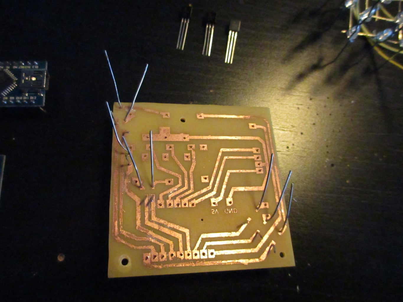
Next we need the circuit board, which I've attached in this instructable. I don't have much experience with Eagle or other designing programs for electronics, so this design is pretty much hand-drawn in Photoshop. It's not very pretty and it's not very good design overall, but it works. The dimensions should be 6cm x 6cm, though, so be careful, when printing it out, that the printer doesn't scale it. I used the toner transfer method to transfer the design to the copper clad board, and then etched it with ferric chloride. There are some great tutorials on this method all around internet, so a quick search should help you a lot if you're not familiar with this method.
If you're going to design your own circuit board, please share it as I'd be glad to see an another design and I'm sure many would benefit from it!
Step 3: Assembling the Electronics

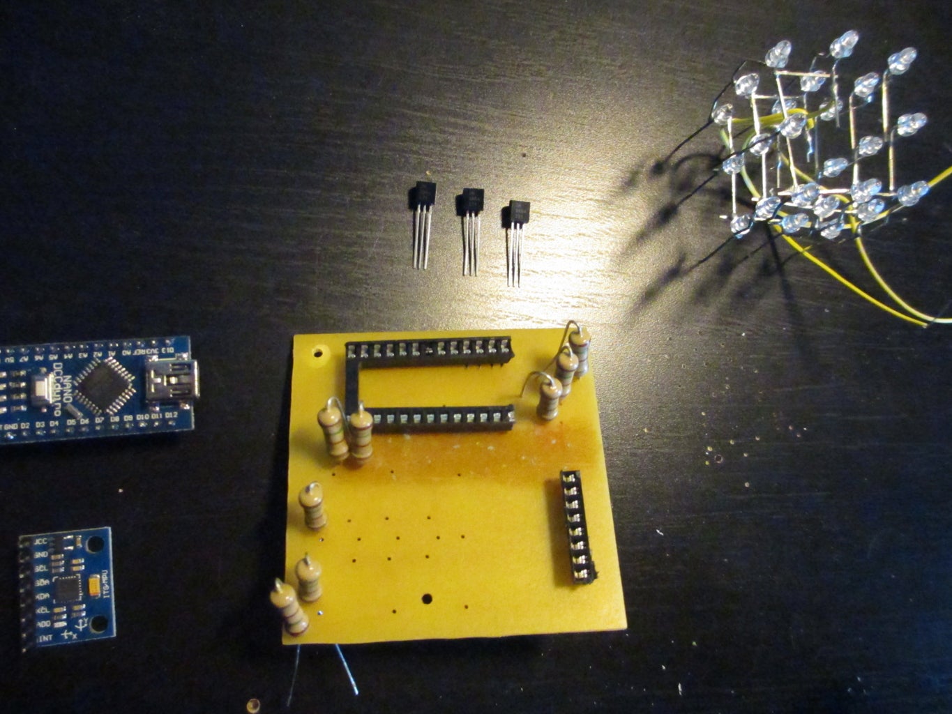


Now we need to attach the Arduino Nano, GY-521, led-cube, transistors and resistors to the circuit board, and the voltage converter and the battery holder to the wooden base. Lastly, we need to attach the circuit board to the wooden base also.
- Drill holes as illustrated in the drawing attached. I used a 0,8mm drill bit for the smaller holes and a 2,0mm for the bigger ones.
- First add the sockets for the Arduino and GY-521 and also put in the resistors. After soldering these, I recommend to check that everything is working. I did this with an additional led, since I don't have a voltage meter. At this point I had to solder a couple of bridges, as some of the lines were broken.
- Next add the transistors and solder them.
- Add the led-cube and solder also it's wires. Note, that in this design a couple of jumper wires are needed, from A to A and B to B. Refer to the illustration.
- Screw the circuit board in to the wooden base through the bigger holes we drilled earlier.
- Also use screws to attach the voltage converter and the battery pack to their respective places.
That's about it, now all we need to do is write some code and wrap the electronics inside a plexiglass cube.
Step 4: The Code
The idea behind the code is pretty straightforward: wait until enough movement is detected and then light up the leds for 30 seconds.
#include <Wire.h><br>
const int MPU=0x68;
int16_t GyX,GyY,GyZ,oldGyX,oldGyY,oldGyZ;
const float a = 0.7;
const float b= 1.3;
void setup(){
  // setup Wire
  Wire.begin();
  Wire.beginTransmission(MPU);
  Wire.write(0x6B);
  Wire.write(0);
  Wire.endTransmission(true);

  // setup leds
  for(int i = 3; i < 11; i++) {
    pinMode(i, OUTPUT);
    digitalWrite(i, LOW);
  }

  pinMode(A1, OUTPUT);
  pinMode(A2, OUTPUT);
  pinMode(A3, OUTPUT);
  digitalWrite(A1, LOW);
  digitalWrite(A2, LOW);
  digitalWrite(A3, LOW);

  Serial.begin(9600);
}
void loop(){
// store previous values
oldGyX = GyX;
oldGyY = GyY;
oldGyZ = GyZ;
Wire.beginTransmission(MPU);
Wire.write(0x43);
Wire.endTransmission(false);
Wire.requestFrom(MPU,6,true);
GyX=Wire.read()<<8|Wire.read();
GyY=Wire.read()<<8|Wire.read();
GyZ=Wire.read()<<8|Wire.read();
GyX = map(GyX, -5000, 5000, 0, 1000);
GyY = map(GyY, -5000, 5000, 0, 1000);
GyZ = map(GyZ, -5000, 5000, 0, 1000);
Serial.print(GyX);
Serial.print("-");
Serial.print(GyY);
Serial.print("-");
Serial.println(GyZ);
if(oldGyX*a > GyX || oldGyX*b < GyX
|| oldGyY*a > GyY || oldGyY*b < GyY
|| oldGyZ*a > GyZ || oldGyZ*b < GyZ) {
cycleLeds();
}
delay(500);
}void cycleLeds() {
// analog pins
uint8_t aPins[] = {A1, A2, A3};
unsigned long exec_time = 0;
unsigned long start = millis();
while(exec_time < 30000) {
for(int j = 0; j < 3; j++) {
digitalWrite(aPins[j], HIGH);
for(int i = 3; i < 11; i++) {
digitalWrite(i, HIGH);
digitalWrite(i, LOW);
}
}
exec_time = millis() - start;
}
}Step 5: Building the Rest of the Box
At this point all we need are the walls and the roof out of plexiglass.
- Cut four pieces that are as wide as the wooden base, and I chose the height to be 10cm. Remember to add the thickness of the plexiglass to the width, so that you get nice sharp corners.
- Cut a piece, that is the same size as the wooden base, but add again the thickness of the plexiglass to every side.
- Glue everything together, and we are done!
That's it, now you have your own motion activated nightlamp!

Participated in the
Make it Glow!


