

Introduction: Motion Sensing Arduino Laser

NOTE: This project was designed in a way that all parts could be reused in future projects. As a result, the final product is less stable than it would be should you use more permanent materials such as glue, soldering, etc…
Warning: Do not place the laser at eye height as it could cause retinal damage.
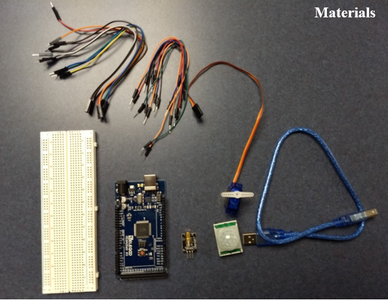
Materials
- Arduino (Mega 2560)
- Breadboard
- Motion Sensor (HC-SR501)
- Laser Module (ST1172)
- Servo Motor (SG90)
- Male to female wires
- Male to male wires
- Paper towel roll
- Duct tape
- Zip ties
- Base
- Scissors
Step 1: Secure Items to the Base


Attach a rolled piece of tape to the bottom of Arduino board and, if necessary, the bread board.
Attach tape to the three sides of the servo motor without wires.
Attach Arduino board, bread board, and servo motor to base.
For additionally stability you can tape down the Servo Motors wires.
Step 2: Wire Components


For diagrams and visuals see the images above. For input and output wires the exact pin you use does not matter; however, if you wish to use our code without making any changes, you must use the pins we specify. For ground (negative) and positive any pin on the bread board, as long as they are in the columns that the Arduino ground and power are wired to. The colors specified below match the color of the wires we used in our images.
- Wire the breadboard to the arduino
- Orange - 5v on Arduino to positive on breadboard
- Black - GND (ground) on Arduino to negative on breadboard
- Motion Sensor
- Brown - Ground(negative) on bread board
- Orange - Positive on bread board
- Red - Input/Output 14 on Arduino
- Servo Motor
- Red - Positive on bread board
- Brown - Ground (negative) on bread board
- Orange - Input/Output 4 on Arduino
- Laser
- Blue - Ground (negative) on bread board
- Yellow - Input/Output 10 on Arduino
- Green - Positive on bread board
Note: When wiring the motion sensor and laser be sure to use longer wires, otherwise the wires may be pulled out of place as the turret swivels from side to side.
Step 3: Attach Cannon to Motor


Poke two sets of parallel holes into paper towel role at one end.
Thread two zip ties through the holes, one zip tie through each set of holes.
Attach paper towel roll assembly on top of servo motor and tighten zip ties around the crossbar on the motor.
Due to uneven weighting, the paper towel roll may tilt forward and point down. To fix this we put additional zip ties between the motor and paper towel roll for additional stability.
Step 4: Attach Motion Sensor and Laser Module to Turret


Attach motion sensor to end of paper towel roll as shown in the above images. Secure it firmly so that as the turret swivels it does not move.
Secure laser to top of paper towel roll as shown in the above image.
Step 5: Arduino Code

Below is a link to a github repository containing the arduino code for this project. If any different input/output pins are used the code will need modified to reflect this. In addition you will have to download all the relevant libraries referenced in the code.
https://github.com/ArduinoToys/ArduinoMotionSensin...
Note: If you need assistance setting up your arduino go to https://www.arduino.cc/


