

Introduction: Multiple IR Temperature Sensors - MLX90614

This is a quick guide on how to set up multiple MLX90614B contact-less temperature sensors via the I2C bus with an Arduino uno and display the readouts on the serial monitor of Arduino IDE. I'm using the pre-built boards, but if you buy the sensor by itself you will need pull up resistors for the I2C bus and a decoupling capacitor between Vdd and Vss.
I highly recommend checking out the datasheet form Melexis because I won't be going into details of all the specifications and tolerances of the senor.

Supplies
x1 Breadboard
x8 Jumper Wires
x6 Jumpers
x3 MLX90614 contactless temperature sensors
x1 Arduino UNO R3
(If you have the MLX90614 without the board)
x2 (4.7k ohm resistors)
x3 (.01 uf Capacitors)
Step 1: Only Wiring One:

The diagram above is based on the datasheets recommendations for standalone sensor. If you have the sensor with the prebuilt board then you wire SLC from the board to the A5 pin on the Arduino, SDA to the A4 pin, Vin to the 3.3V pin, and the GND to the GND terminal on the Arduino.
We are going to need to change the address of the senor if we want to use multiple sensors on the same I2C bus, but you can only reprogram one at a time.
Step 2: Changing the Address(Coding)
Luckily for us all of our coding need in this project there are libraries for each step.
You can either find the sparkfun library in the "Manage Libraries" under tools by sreaching for the MLX90614 in the Arduino IDE or you can copy the folder I provided in the zip file to "Document/Arduino/libraries" on windows.
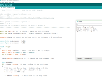
The file is called "MLX90614_Set_Address.ino" or you can find the "set_address" file under the "examples" drop down in the IDE. After all that its fairly straight forward, the default/factory address is "0x5A" and then for the "newaddress" variable you can change it to whatever address you desire given the limitations of the datasheet and just make sure they all differ from each other. Upload the code to the Arduino, open the serial monitor under tools and type "e" into the serial monitor and hit enter, it should prompt you that the address has changed and to disconnect the MLX90614 from power.
Step 3: Wiring All the Sensors:

Same method as last time if the you have the standalone sensor follow the diagram above, if you have the boards then you can chain them together and then connect the last one as if it was a single sensor to the Arduino.
Step 4: The Final Coding:

For actually running the sensors I had to modify the library from Adafruit to run the multiple sensors, thus you will need to install the library manually from the zip file I provided, i.e move the folder "Adafruit_MLX90614_Library" into your Arduino libraries folder as mentioned in step 2. Next, open "SiMlx.ino" and make sure the addresses match with the ones you've changed your sensors to, then pass those addresses separately and sequential through the "mlx.AddrSet()" template I've provided. Upload it to the Adruino and it should print out to the serial monitor as seen above.
I set up only three, but you can have more by copy and pasting each code block, defining more address and changing the number of sensors for the average, if you want an actuate average.
I found the sensors to be fairly accurate as long as I didn't have them wired to far from each other.
Good luck.


