

Introduction: Munny Touch Mood Light and Speaker


This project idea came to me when my friend suggested we design/decorate a Munny. I had never heard of these little figurines prior to this so naturally, I did a quick Google search to see what they were all about and what others had done. I stumbled upon a few designs where people had built tweeters out of the Munnies which appealed to my inner engineer.
I happened to know someone looking for a bedside lamp AND a small speaker for their iPod... I was also just itching for a fun little project to kick off the dreary six month winter season. It seemed the conditions were just right to turn this Munny into a music-playing light show!
Here's a quick video of what the finished product did:
Step 1: Tools & Materials

Tools
* Decent soldering bench:
Cutters, Strippers, Tweezers
Helping hands
Assorted wires
Soldering Iron
Solder Wick
* Sharp knife
* Drill
Materials
* Mini Munny (you can get cheaper ones at the dollar store)
* Access to a good electronics supplier (ie. Digikey)
* Prototyping supplies (resistors, capacitors, breadboard, jumpers, etc)
* Electrical Tape
* Super Glue
I visited my local electronics store to pickup the audio amplifier and a speaker to do a quick and dirty proof of concept on the audio circuit which I did not have much experience with. After that I made my schematic and did my best to order all the parts I thought I would need in one shot from Digikey.
Total Cost: $30CAD (Munny itself was kind of pricey at $14)
Step 2: Initial Prototype

The audio amplifier was the aspect of this project that I was most unfamiliar with, so before I started anything I decided to prototype that based on some circuits I found online. I connected the a basic circuit with minimum gain, fed in one channel of audio from my laptop and to my surprise the circuit worked quite well and tiny speaker I had bought actually provided decent volume! So far so good :)
Step 3: Schematics


With the initial prototyping out of the way, and confident that the sound I could produce would be sufficient for my application I proceeded to make the schematic. This is where the majority of the design came together. Here's a quick breakdown by each block:
Power Supply
I had initially hoped to power the whole system of 6V with the option of using some button cell batteries. However, in the end I opted for a 9V supply because they were more common and allowed me to place 2 LEDs in series in order to reduce my system current. I used a basic 5V regulator (for the micro-controller supply) with a lot of extra filtering on the input because I was driving the audio circuit directly from the 9V.
Audio Input
I only had one speaker but I wanted to be able to play back both audio channels on it. After some research I found that most devices should be able to handle just shorting the two inputs together but it's better to add some resistance. I settled for 47ohms (I wanted it to be more or less on par with headphone impedance that my device would be expecting) and it seemed to work well.
Audio Amplifier
I modified my original basic amplifier circuit to make it a bit more robust. This configuration is taken from the LM386 datasheet and works well. Notice the extra capacitance on the supply pin- it is very important to have some capacitance very close to this pin on your board.
Control Circuit
After much deliberation about the features I wanted to implement I decided that I would need three PWM channels (for the three LED channels) and two digital I/Os- the ATTINY85 which I had worked with before would have enough ports, and it can be programmed using the arduino environment/libraries. The touch sensor is simply a metal plate.
LED Circuit
I initially had three sets of RGB LEDs in parallel, driven by the 3904s. After the first prototype I decided to add a fourth LED and bump up the supply voltage to 9V so I could place two of them in series. Note: I had to order new LEDs for this because the ones I bought initially were common anode which prevented me from being able to control all three channels when wired in series so keep that in mind if you're planning on doing something similar.
Step 4: Prototyping


Once my schematic was complete I placed an order and started to prototype the circuit on a breadboard. I was able to fit the whole system on a single board so I was hoping that it would be a fairly good approximation of the final build.
With everything connected up here and the voltages on the IC looking okay, it was time to move on to programming my ATTINY.
Note: I'm using a few potentiometers still here to dial in the values for some of my resistors. I also had intended to use two potentiometers in my initial design to adjust volume/brightness but this feature didn't make it to the final product.
Step 5: Software/Programming

It had been a while since I'd done any AVR programming but the Arduino platform really does make things super easy. I decided to pull the ATTINY out of the bread board and fly-wire in the pins from the Arduino Uno dev board to debug my code. After a quick sanity check of toggling the LEDs I was off!
Touch Logic
One of the "cool-to-have" features I wanted to implement was the capacitive touch switch. I'd never worked with this kind of input before, but once again the arduino libraries made it really simply. You can download the library I used here: http://playground.arduino.cc//Main/CapacitiveSensor?from=Main.CapSense . Just extract it and copy it to your libraries folder in your Arduino install directory.
I simply added latching functionality so that the state of the system would invert one each touch & release.
The premise of the touch sense is simple enough. The IC drives the Tx pin high and then times how long it takes for the Rx pin to go high as well. As you bring your finger closer to the metal touch plate, you add capacitance to the line and the time it takes for Rx to go high increases. By playing with the thresholds you can tune the code to work with your sensor.
LED Randomizing
I found some clever and some not so clever ways of randomizing the fading of the LEDs. However, even the best one's I found had two main flaws in my mind:
1. The LED's spent too much time in transition and on white
2. Occasionally the three channels would pass through a value of 0 which would cause a brief, but very annoying flicker of darkness.
To avoid these and other minor grievances I opted to go with my own design. What I did was instead of randomizing the 3 channels, I created an array that contained 13 different colours that I liked and then transitioned smoothly between random entries in that array. This way I was able to avoid all the LEDs turning off at the same time, specify how fast they transitioned and how long they "rested" on each colour, and I could bias certain colours that I liked more.
Once I was happy with the code on the Arduino, I simply changed the pin definitions to correspond to the ATTINY, programmed the IC using the Arduino (see link: http://hlt.media.mit.edu/?p=1695), and then put the ATTINY back on my breadboard.
The attached code has a lot of debugging print statements and some older functionality that I removed but I tried to comment thoroughly. Let me know if you have any questions or comments!
See code attached (I had to rename the arduino .ino to a .txt because it wasn't letting me upload otherwise)
Attachments

Step 6: Building the Board


Transferring my circuit to a perf board presented a bit of a challenge due to the very tight spacing constraints. I planned on putting one board in the head of the Munny and the other board in the body and run a few wires between the two. In order to plan the layout most efficiently I suggest drawing out the perf board size on some grid paper and arranging components on there.
In my first design I made two boards that sandwiched together but this didn't end up being a very good solution. In the end with some more careful planning I was able to fit everything on one board. You may have to get quite creative with your component placement- I ended up using some SMD resistors in order to squeeze them between pins of the IC. I had roughly an 8x13 grid to work with (0.8"x1.3" on 0.1" spacing perf board).
Step 7: Assembly


One of my primary goals for this project was to keep the Munny looking as clean as possible and to make it fairly robust. Because of this I ended up having to ditch my idea to connect the arms to potentiometers and use them as volume/brightness control- they were just too fragile and had unsightly gaps between the arm and body.
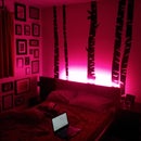
One of the issues I ran into here (other than the total lack of space) was that the LEDs weren't diffusing as nicely as they were when I was breadboarding the setup. On the first prototype the effect was quite bad with bright spots in some places and components casting shadows everywhere.
On the final design I took care to move the LEDs as far away from the surface they were pointed at to allow the light to diffuse. I also made sure no wires ran between any illuminated surface and the light source. Finally, I made one of the LEDs in the body aimable in order to be able to shine it towards any dark spots.
With these changes, the lighting was much more pleasant.
After installing all the electronics I super-glued the speaker into place and the rear panel I removed. Finally I wanted to put the Munny on a platform that would help him balance and also act as a large touch sensor that would be easy to find in the dark. I repurposed a Zelda shield mint tin for this. I sanded and polished the surface to create a good contact between the tin and the foot of the Munny and then epoxied a strong magnet in there with some clear epoxy to hold him in place along with a nice photo of myself and the giftee to give it more of a personal touch.
Note: you may need to recalibrate your touch sensor as I did which is a real pain. Try to do your debugging with as similar a sensor as you plan to use in the final product to avoid this.
Step 8: Final Product

I hope you've enjoyed the Instructable- feel free to leave any comments, questions or suggestions!

Participated in the
Make It Glow Contest

Participated in the
Holiday Contest

Participated in the
Hardware Hacking


