

Introduction: My First Synth


The kid synth came about as I sat hunched over a tangled mess of synthesizer wires. My friend Oliver came over, assessed the situation, and said, "You know you have succeeded in making the world's most complicated children's toy." While my initial reaction was to grunt at him, and shoo him away, I later realized that he did have a point. The synthesizer I was working on would make a good kid's toy. So, I took a detour from finishing my big boy synthesizer and embarked on making a child's toy for my one year old nephew.
I designed the synthesizer to have direct feedback, bright colors, and big parts. This makes it easy to understand, easy to use, and fun for children of all ages. Even if the person using it does not quite understand what all of the buttons and knobs are doing, it is fun to just smash buttons, and flick switches and listen to the sound change.
Overall, I am pleased with how this came out. I am hoping that my nephew will enjoy playing with this half as much as I do.
Step 1: Kid-Friendly Design

Making a kid's toy proved to be an interesting design challenge. It not only had to be fun and inviting to a small child, but also virtually indestructible and safe to play with. This meant that I had to minimize the amount of detachable parts, and make it difficult for a child to take apart.
For starters, I decided to use big colorful arcade buttons because of their sturdy construction and inviting appearance. I tested this theory on the Instructables resident toddler and she seemed more than pleased to smash away at the button panel, whether or not the buttons did anything. I next decided to replace the switches, sliders, and potentiometer knobs with home lighting fixture parts. From my experience, I find that small children like to play with light switches and other big buttons. Unfortunately, they were not very colorful and inviting. I solved this problem by adding colored resin to the tops of each of the knobs.
The power switch was also a challenge. I wanted it to be easy enough that my nephew could feasibly use it himself, but difficult enough that he would not get the immediate feedback of turning the synthesizer on and off repeatedly (which would defeat the point of all other switches). I resolved upon a lamp pull switch for this task. Toddler testing thus far has proven successful.
One more thing I had to keep in mind was how to make changing the battery easy enough my sister could do it, but impossible for my nephew. I didn't want him to be able to get into the case and tug at the wiring. I resolved to use a hatch system with two child-proof magnetic latches. In order to get into the inside of the case, you need to know to carefully place a magnet on two specific places on the hatch. This makes the case both seamless, and easily accessible (to those in the know).
The one weak point in the case is the speaker grill. I considered reinforcing this with a metal mesh, but ultimately decided against it. I'm just hopeful he won't try to jab anything long and skinny inside the holes. I did, however, water seal speaker cone, because - well - you never know.
Beyond that, I simplified the synthesizer circuit that I was working with to only include functionality that gave immediate or near immediate feedback. While some knobs may not work when some of the switches are toggled, my nephew will never be far from making it create some sort of noise, or toggling it back into some sort of highly playable state. This makes it fun enough for a toddler to wail away on, but complex enough that it will still be rewarding as he gets older. This toy is compelling to children of all ages.
Step 2: Go Get Stuff

You will need:
(x1) 24" x 36" x 1/4" maple plywood
(x1) 6" x 6" x 1/16" acrylic
(x9) Light dimmer knobs (white)
(x2) Dreambaby Magnetic Locks
(x1) Radioshack Mini Amplifier
(x1) Lamp pull-chain switch
(x8) SPDT arcade button switches
(x8) Light toggle switches (4 white - 4 black)
(x1) Light dimmer / slider
(x1) 76477 sound generator IC
(x1) 76477 adapter board
(x1) 555 timer
(x1) 4017 decade counter
(x1) LM741 op amp
(x1) LM7805 5V regulator
(x1) 10M resistor
(x6) 1M resistor
(x2) 100K resistor
(x10) 47K resistor
(x1) 22K resistor
(x9) 10K resistor
(x3) 4.7K resistor
(x1) 3.3K resistor
(x1) 2.8K resistor
(x4) 2.7K resistor
(x1) 2.2K resistor
(x1) 1.9K resistor
(x1) 1.5K resistor
(x3) 1K resistor
(x1) 680 resistor
(x1) 470 resistor
(x4) 220 resistor
(x4) 1M potentiometer
(x1) 100K potentiometer
(x4) 10K potentiometer
(x3) 100uF capacitor
(x1) 10uF capacitor
(x1) 1uF capacitor
(x5) 0.1uF capacitor
(x1) 5600pF capacitor
(x2) 470pF capacitor
(x4) 10mm LED (assorted colors)
(x6) 1N4148 diodes
(x3 - x4) PCBs
(x1) Red and black solid core wire
(x1) Red and black stranded wire
(x1) 30-NF contact adhesive
(x1) Wood glue
(x1) Polycrylic matte finish
(x1) Clear Resin (I used Ultra-Glo
(x1) Resin pigment (assorted colors)
(x10) Quick release clamps
(x1) Cork mat (12" x 24")
(x1) Resin measuring cups and mixing sticks (need many)
(x1) A bunch of random tools (and whatnot)
(Please note that some of the links on this page contain Amazon affiliate links. This does not change the cost of the item for you. I reinvest whatever proceeds I receive into making new projects.)
Step 3: Cut


Download the attached file.
Load a 2' x 3' x 1/4" piece of plywood into your (school's? friend's? local TechShop's?) laser cutter.
Etch the template into the plywood using the following settings:
power: 100
speed: 80
Do about 10 passes, to get the etching nice and deep. This is largely to countersink the mounting hardware for the electronics.
Next, without opening the machine and jostling the plywood, vector cut the board with the following settings:
Speed: 4
Power: 100
frequency: 500
Note: All settings are for an Epilog Legend 36EXT that has gotten a lot of mileage, and isn't performing quite as well as it used to. Make adjustments as necessary.

Step 4: Breakout Board


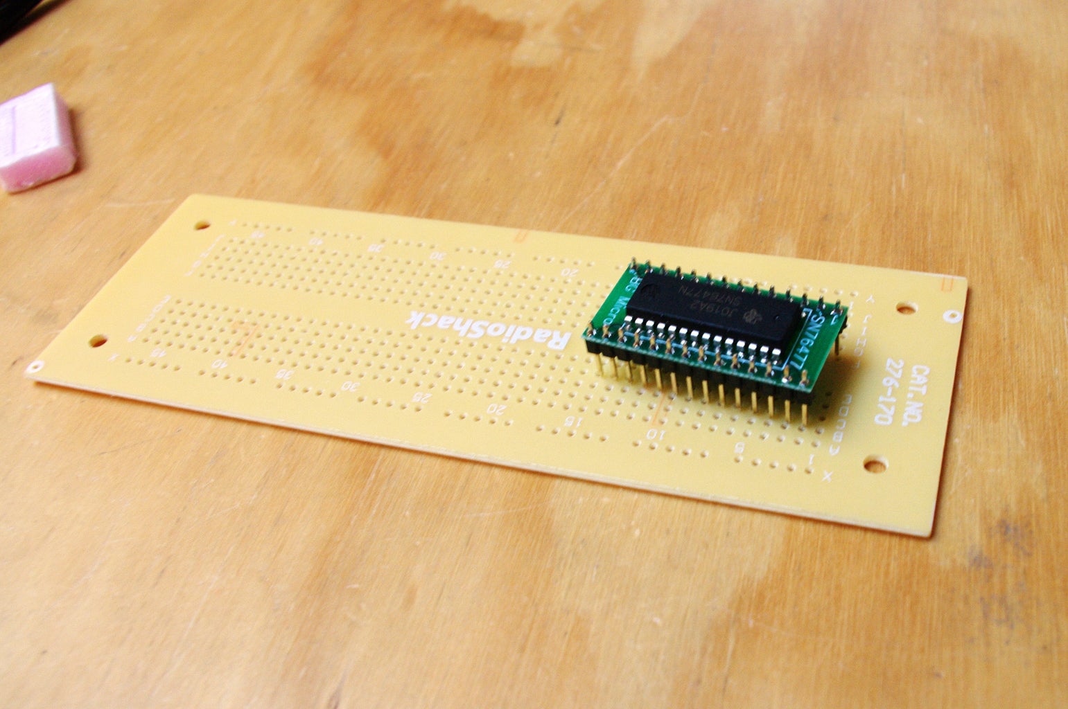
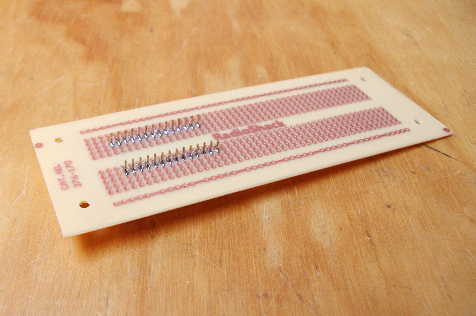
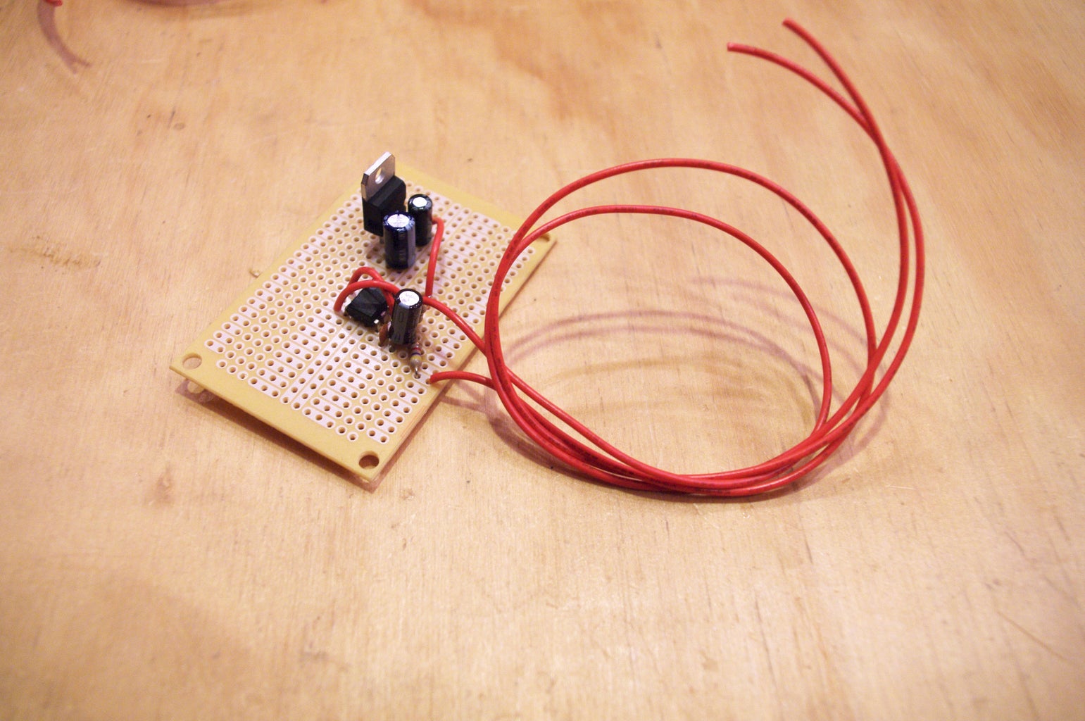
Solder the 76477 to the breakout board. Also, attach male header pins.
This will help to easily attach the chip to a PCB.
Step 5: Build the Circuit


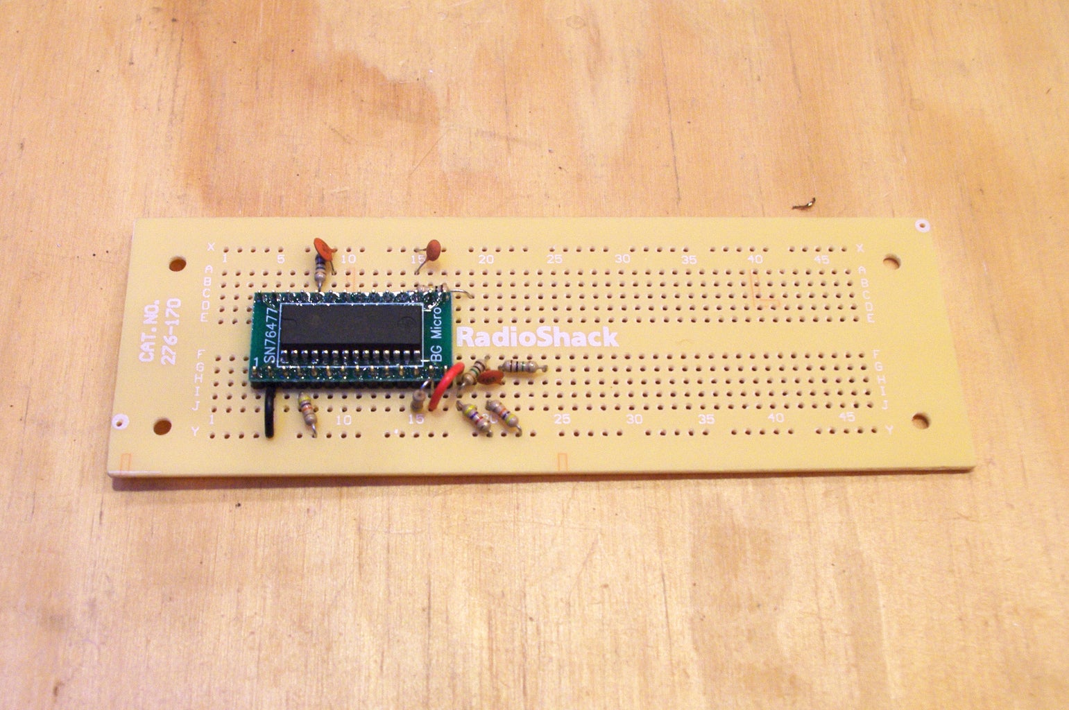
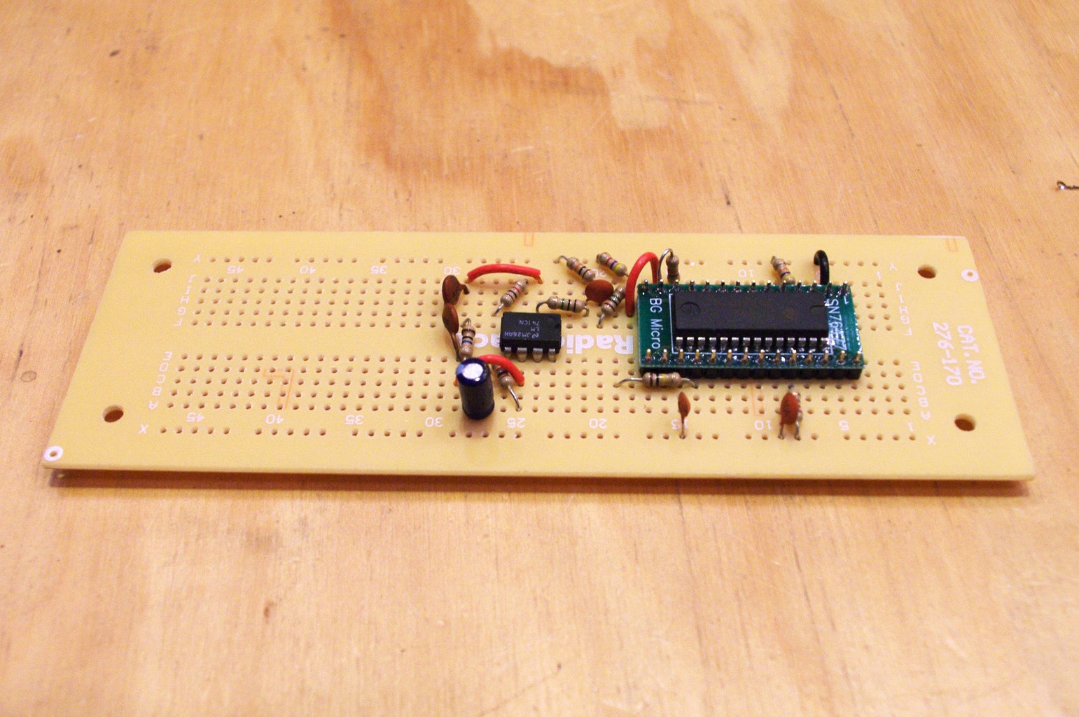
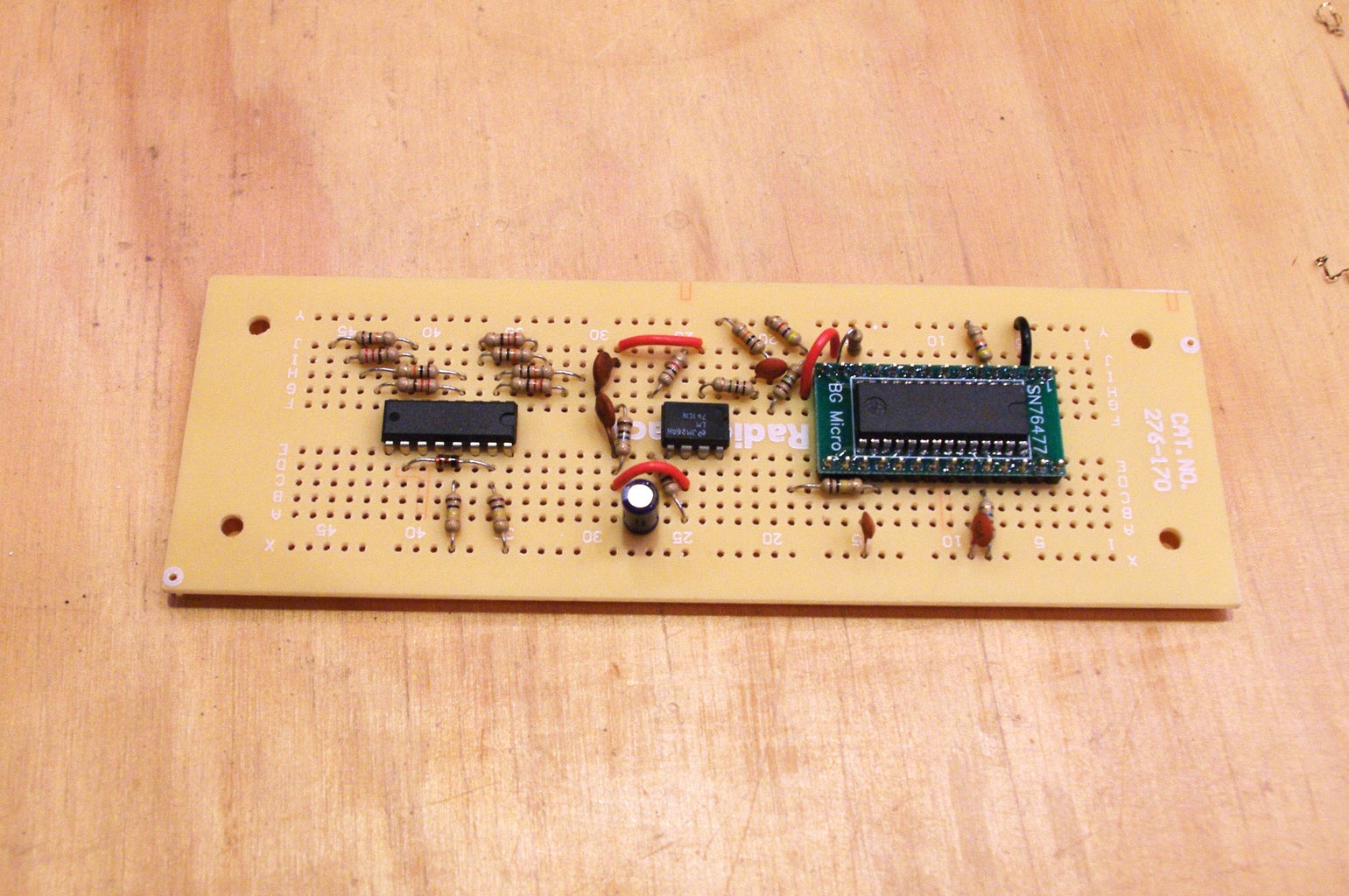


The circuit is built around the 76477 sound generator chip. This chip was used in 1980s arcade machines, and a wide range of electronic toys. It has a built in VCO (voltage controlled oscillator), envelope generator, noise generator, signal mixer, and amp. Since this chip is doing so much, it has a lot of potential to be controlled with external circuitry. However, my goal here was to keep feedback very direct, so I hardwired a lot of the more vague settings a person may want to adjust on the fly (such as note attack and decay). If you are building this for yourself and not a one year old, feel free to mess around with circuit and experiment.
The VCO on the chip is largely being controlled by a series of four potentiometers that are being stepped through in sequence by a 4017 decade counter. The timing for the decade counter is being controlled by a 555 timer chip. This can be sped up and slowed down with a potentiometer. Basically, it is a sequencer. When you change the position of each of the sequencer's knobs, it changes the voltage the 76477 chip receives on pin 16, and this in turn changes the output frequency of the audio note.
Also, between the 4017 step sequencer circuit and 46477 chip are a series of 8 arcade buttons. When you press one of these buttons, it disconnects the sequencer circuit from the 76477 chip. The button then sends its own voltage to the 76477 VCO pin instead. These 8 buttons, are basically hard-wired to form a musical C scale. This allows different notes to be pressed and interrupt the sequencer. There is also a switch which entirely disconnects the sequencer from the 76477 and allows you to play these 8 buttons like a musical keyboard.
The one last key aspect of the main circuit is the low pass filter on the output. This smooths out the harsh square wave being produced by the 76477 chip and makes it a little more listenable. The amount of filtering is easily controlled by a potentiometer, and by turning this knob back and forth rapidly, you can get strange wah-wah effects.
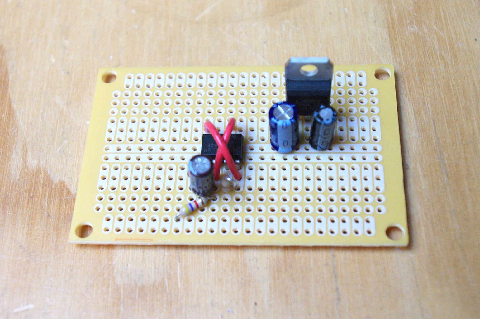
Aside from all of that, there are some components for power regulation. Different aspects of the circuit are operating at 4.5v, 5v, and 9v.
The final output is sent to a modified Radioshack amplifier. The key hack here involves ripping off the rotary potentiometer/power switch. The power switch is then hardwired to be on, and the potentiometer is replaced with a sliding light dimmer.
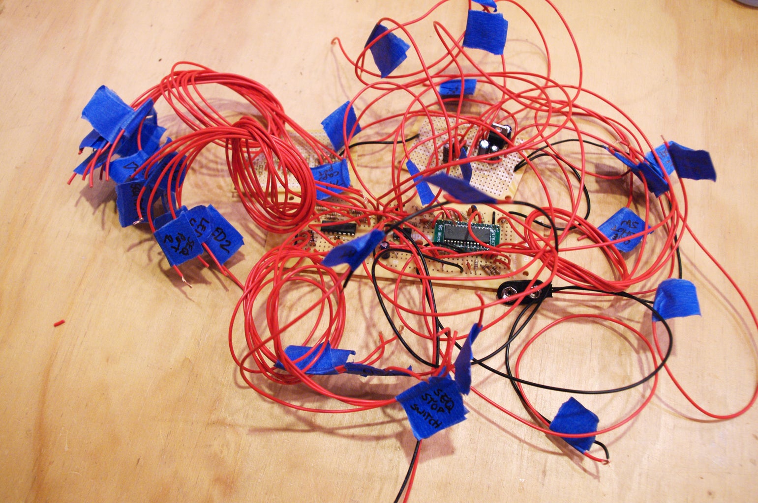
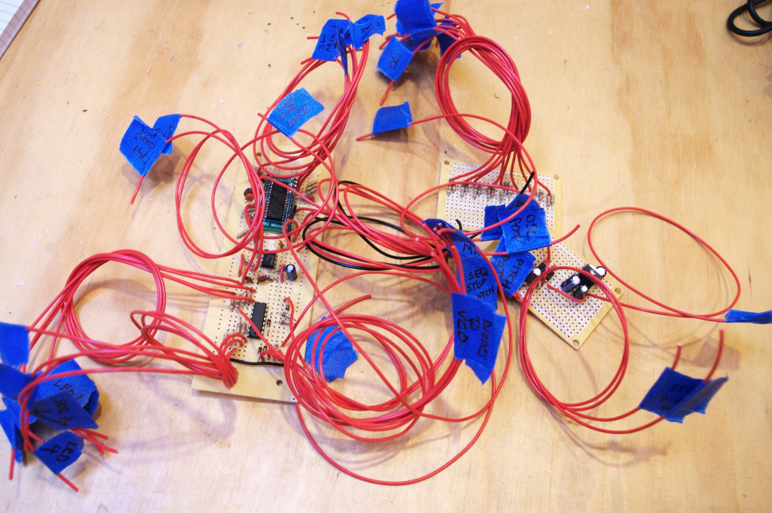
For now, don't bother attaching any components that need to be mounted in the case. However, do attach all of the wires necessary to connect these components later on.
Also, do not forget to label which wire is which! This will prevent future bouts of insanity.
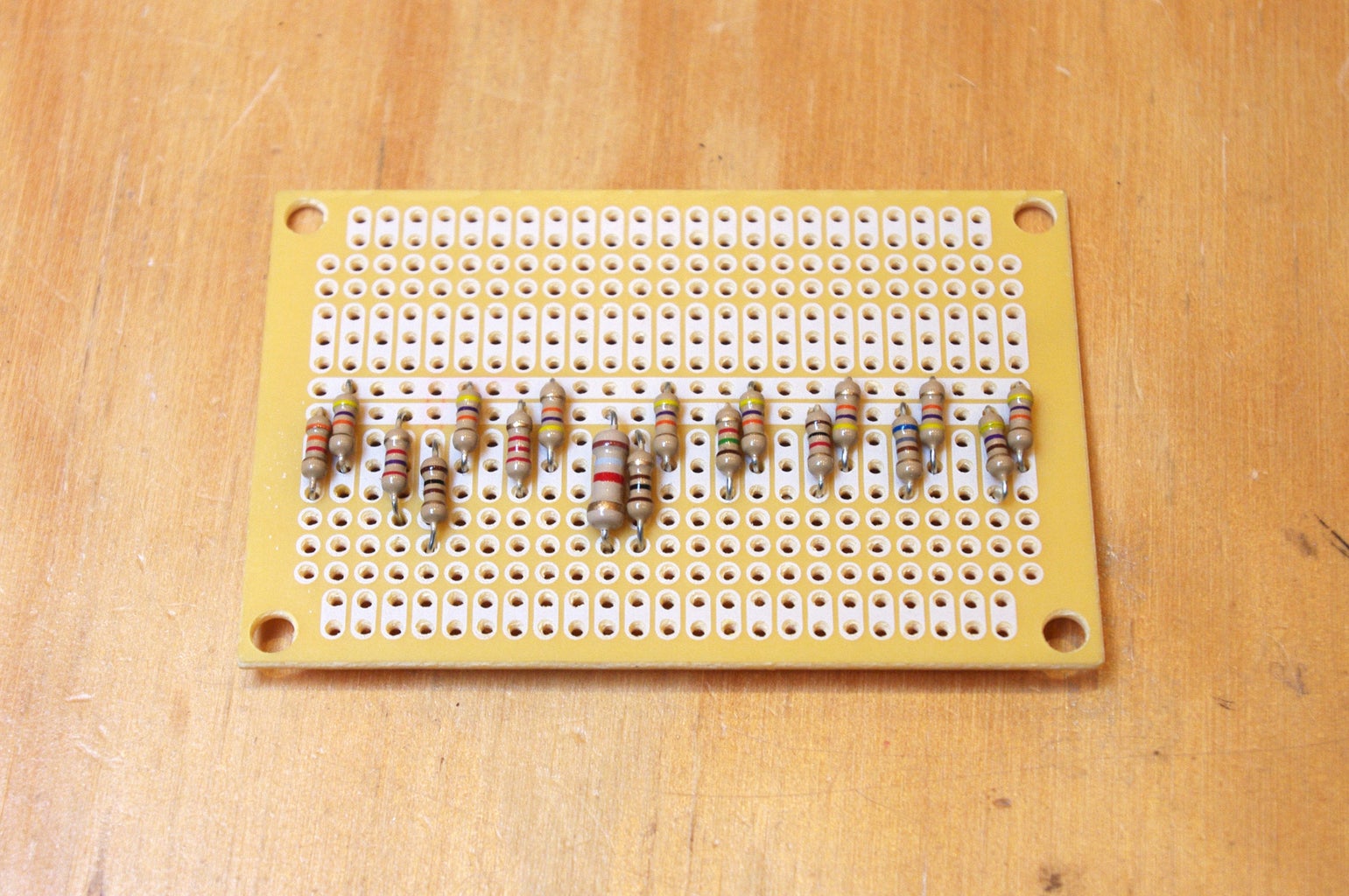
I ultimately used one PCB for the 76477 and the 4017 circuit. I then used one PCB solely for the resistors for the 8 buttons. The last PCB was used to both build out the 555 timing circuit for the 4017 step sequencer, and also to do all of the different power regulation.
Even though you shouldn't permanently attach any of the panel mounted parts right now, the most important thing to do when building the circuit is to test to make sure that your circuit is fully functioning before moving forwards. Once it is mounted in the case, making fixes to the circuit board becomes darned near impossible.
To see a larger version of the schematic click the little "i" in the upper left-hand corner.
Step 6: Mod the Dimmer


Light dimmers are no longer simply large potentiometers that lower the voltage flowing through them. They actually have a whole bunch of circuitry to control the wall current.
Don't worry about why this circuitry is in there (for now). All you need to know is that it all has to be disabled. Cut away every last component from the dimmer's circuit board.
Figure out which pins on the board correspond directly with the dimmer's potentiometer. A multimeter comes in really handy in doing this.
Once you have determined which two pins are connected to each end of the potentiometer, solder a wire to each one.
Step 7: Hack the Amp


Remove the potentiometer / power switch. Desoldering it is kind of a pain in the neck, so it is probably best just to cut it free.
Connect the two ends of the switch together with a section of wire to keep the amp constantly in the on position when power is applied.
Solder a 10K resistor between one of the outer pins of the potentiometer and the center sweep.
Solder a 22K resistor to the remaining pin of the potentiometer.
Step 8: Trim the Light Switches


The light switch should have a few different mounting tabs. The only one we will need are the two threaded inner mounting holes.
As a matter of course, the switches won't fit in the case unless the other mounting holes are sawed off.
So, saw all the switches to be shorter. Any excess metal tabs should be cut away and only the threaded mounting holes should remain.
Step 9: Access Panel


Measure halfway across the shorter length of the mounting panel and make a mark (this should be at 2 - 5/16"). Repeat on the opposite edge, and then draw a line bisecting the panel.
Take the smaller wooden latch bracket, center it along the midpoint line, so that the large hole is closer to the edge.
Glue it flush to the edge of the panel, and then clamp it down. Repeat on the opposite edge.
Once is it is dry, use a 5/16" drill bit and the large hole in the bracket to drill a deeper hole in the wood. However, be careful not to drill all the way through. Repeat on the opposite side.
Once the holes are drilled deeper, mount the magnetic latches flush with the wood and fasten them in place with wood screws.
Step 10: Start the Bottom


Glue the bottom bracket to the inside of the bottom of the case such that the opening in the bracket is perfectly centered atop the hole in the bottom of the case.
Step 11: Finish the Bottom


Mount the brackets for the magnetic latches to the bottom panel, flush with the narrow edge. These should be positioned so that they line up directly with each of the latches.
If the bottom panel appears to be a little loose, put a thing spacer (around 1/16") between the brackets and the bottom panel to raise it up a little. Continue doing this until the panel cover is flush with the bottom of the case, but not so tight that the latches stop working.
Additionally, glue on the extra wooden mount for the battery holder.
Finally, glue down all of the 1/4" spacers to the inner bottom bracket, such that they correspond with the mounting holes for the PCBs.
Step 12: Mount Everything


Mount the circuit boards atop the appropriate spacers using wood screws.
Mount the battery holder atop the battery holder bracket using a wood screw.
Insert the bottom panel into place. It should be a snug fit. If it is too snug, sand down the sides of the panel and the sides of the opening.
It is very important that the panel can freely be inserted and removed from the case by way of magnets. Now is the time to ensure that you will be able to get the panel off later when the case is very firmly sealed shut... so... Make sure it works before moving forwards!
Step 13: Seal the Speaker Cone


I decided to waterproof the speaker cone... just in case. It should remain waterproof so long as my nephew does not jab anything into the speaker grill and puncture the cone. So, hopefully he will just spill things in there and not jab long, skinny, sharp, objects through the holes in the grill.
To waterproof it, basically paint on two to three thin coats of water-based polycyclic. That is all there is to it. It stiffens the cones a bit, but I found it didn't noticeably change the sound.
Step 14: Solder the Buttons


While the case is not yet assembled, this would be a good time to prep the buttons for mounting.
Install them in the front of the case, attach the corresponding switches, and solder them together as appropriate.
Also, labeling them right now, as to which note corresponds to which switch, will save you from confusion and headaches later.
Remove the switches from the buttons, and the buttons from the panel, when you are done.
Step 15: Solder the Pots


Position the potentiometers for the sequencer in the panel of the case and solder all of their common ground pins together with black wire.
Position the three potentiometers for the 76477 which have a common ground pin into the case's panel. Solder the common ground pins together with black wire.
Step 16: Prep the Front


Center the large round hole of the front panel bracket atop the speaker grill.
An easy way to do this is to line up the smaller LED holes with the smaller LED holes on the front panel. Insert the LEDs to line the two up. Once perfectly align, glue and clamp the bracket to the underside of the front panel.
Once clamped, remove the LEDs and clean off any glue that may have gotten on them.
Let it dry.
Step 17: Mount the Speaker


Affix the amp's speaker cone into the large opening of the front panel bracket using Fastbond 30-NF contact adhesive. Follow the directions on the label's adhesive to ensure a strong permanent bond.
Step 18: Mount the Amp


Glue 1/4" spacers around the speaker cone such that they correspond with the amp's mounting holes.
Place the amp board atop the spacers, and affix the amplifier board to the back of the front panel using wood screws (not pictured).
Cut away the 9V battery connector, and extend its wires away from the board. Use shrink tube to insulate the solder point.
Solder a black wire to the 22K resistor and a red wire to the center terminal that corresponds to the center sweep of the potentiometer.
Step 19: Build the Box


Gluing the box needs to happen quickly and accurately. I started by lining up the four side pieces and made sure they fit properly with the top and bottom.
I then cut up a cork mat into small pieces, which I was planning to use to protect the case from being damaged by the clamps.
I started by gluing two sides of the case together, being careful to spread glue thinly with a paintbrush on both surfaces that were joining together.
From there I rapidly finished attaching all of the sides of the case together in a similar fashion.
I lightly clamped the sides together to keep them from falling apart (being sure to use my cork protector pads).
Next, i glued around the upper edge of the frame and the top piece and mounted that on.
Finally, I glued the bottom on.
I clamped all of the sides together using many - many - bar clamps, in order to apply a uniform pressure on all surfaces (as best I could).
Fortunately, TechShop had an excess of bar clamps of various shapes and sizes.
Step 20: Sand


First, let me say thank goodness for the belt sander in the wood shop at TechShop. This tool saved me a lot of time and frustration.
Basically, I gently rounded all of the edges of the case using a belt sander.
My initial goal was to sand away all of the dark tabs on the side of the case. However, as I started to round out the edges, I noticed a very nice checkerboard pattern start to emerge. I decided to keep the alternating dark and light tabs.
Nonetheless, I made sure each edge was nice and smoothly rounded.
Step 21: Stain


Put an even coat of polycrylic water-based sealant on all of the outer surfaces of the case (including the bottom panel).
To get at all of the surfaces at once, you can use a block of wood (or two) placed on the table beneath the case to serve as a pedestal to hold it aloft. Just make sure that the blocks of wood fit inside of the bottom panel on the case and does not touch the outer surfaces.
After the first coat dries, lightly sand it, wipe it clean and put on a second coat.
After the second coat dries, lightly sand it once more, wipe it clean and put a third coat.
Let this final coat dry for a good while to prevent any smudging.
Step 22: Finish Wiring and Mount Everything


I'm going to put this out here from the onset. Mounting the hardware in the front panel is extremely difficult and infuriating. It is very hard to get your arm inside of the case, and things need to be mounted in a logical order.
That said...
I found the best thing to install first were the outer four buttons (in the bottom left corner). Install these buttons half way. Next solder the appropriate wires onto the button's corresponding switches, and then install completely.
The next thing I installed was the four potentiometers for the sequencer. Again, I soldered the appropriate wires first, and mounted them from the edge of the case towards the middle.
Once those were in place, I mounted the power switch. The power switch mounting was just deep enough to mount flush with the front of the case. I planned on this from the onset and did not bother trying to countersink the mounting nut. Instead, I epoxied the switch in place from the inside. I also cut a small block of wood that fit between the switch and bottom of the case. I then glued this piece of wood in place to prevent the switch from ever getting pushed out. Let's just hope it never breaks, because it is going to be darned near impossible to remove.
After the power switch was in place, I soldered the LEDs to the circuit and epoxied them all in place.
Finally, I mounted the final four color pushbuttons in place to complete the left side of the case.
I then moved onto the right side of the of the case.
Starting from the top right of the case and working my way down and left, I wired up and installed the first four switches. This was an infuriating pain in the neck.
I then wired up and installed the remaining potentiometers starting from the bottom right.
Once the potentiometers were all firmly in place, I installed the remaining four switches.
Finally, I wired up and installed the volume knob, and breathed a sigh of relief.
Step 23: Power


Plug your battery in and place it in the battery holder.
If all went well, it should now be turned on and making noise.
If it not turned on, try pulling the power switch. That should help.
If it's not working. Try a new battery.
If it is still not working, try to debug as best you can.
You did heed warning to the bold and italicized note on step 5 which said to make sure everything was working before moving forwards, right?
Step 24: Drill the Knobs


Most dimmer knobs are designed not to be interoperable. In other words, they all have annoying plastic notches in them which prevent them from being put on a generic potentiometer.
To fix this, drill out the mounting holes of the knobs using a 1/4" drill bit. Be careful not to drill all the way through the knob. The goal here is just to hollow out the mounting hole.
Step 25: Prep the Knobs


To ensure the colored epoxy sticks well to the knobs sand the top surface and drill small shallow holes around the inner lip of the knob using a 1/64" drill bit.
The sanded surface and holes will create a good surface for the epoxy to grip to, and ensure it won't fall out later.
That said, I am not sure any of this is even necessary. In the test I did with an unmodified knob, the epoxy appeared to grip to the knobs pretty well. However, I prepared the knobs anyhow because I didn't want to take any chances that it might pop out at a later date and pose a choking hazard.
Step 26: Add Color


Mix the epoxy at the ratio specified in a large batch.
Pour this large batch into smaller mixing cups and then add pigment until the mixture is thoroughly opaque.
You can mix together different primary-colored pigments to get a range of different colors.
Carefully pour a small drop of colored pigment onto the top of the knob. Wait for it to spread out. After a moment, help it along by gently spreading it with your mixing stick, until the whole ring is filled. If there is not enough epoxy to spread out evenly, add a tiny bit more.
Let it set for 5 minutes. If your epoxy has instructions for removing bubbles, now would be the time to do that. Mine, for instance, required that I exhale on the surface of the drying epoxy. Others sometimes suggest gently jostling the drying surface to disturb the bubbles. Read the instructions for your epoxy and proceed appropriately.
Leave it to dry in a warm, clean, place for the amount of time specified in the instructions. For best results, don't skimp on the drying time.
Step 27: Finishing Touches


Place the colored knobs onto the synthesizer's potentiometers as your see fit.
Step 28: Opening the Case


Opening the case is a little tricky on account of the magnetic locks, but not impossible.
To do this, first unlock one with magnetic key and pull up that side and hold on to it (so it doesn't lock in place). Next, use the magnetic key to loosen the lock on the other side. The whole panel should now come loose.
When putting the lid back on, make sure the grain of the wood lines up.
Step 29: How to Use

Roll over the text boxes on the graphics to see what each part is
The metal power cord pull turns the synthesizer on and off.
The speaker is where the sound comes out of.
The volume slider adjusts the loudness of the volume.
The sequencer LEDs show which of the sequencer knobs is currently making audio. The color LED that is lit up is the same color as the knob currently controlling the audio.
The colorful piano buttons allows you to interrupt the sequencer and play your own notes. By toggling the sequencer toggle switch, you can turn off the sequencer and play only the piano buttons.
The top row of switches controls the internal mixer and the comparator. Flicking them changes the sound the synthesizer makes.
Note about the mixer: When all of the mixer switches are in the down position, the synth will stop making noise. To fix this, flick one up. Different combinations of these switches may disable pulsed-tone mode and the noise control.
The bottom row of switches does the follow (from left to right):
1) The sequencer toggle turns of the sequencer for piano button-only mode
2) The note repeat switch stops the sequencer in the first position, and lets you control the sound with the blue knob.
3) The one-shot switch toggles one-shot mode on and off. This is the difference between long discreet notes from the sequencer and short staccato notes.
4) The pulse-tone knob toggles the pulse-tone knob on and off. This only works in certain configurations of the mixer switches.
The bottom group of knobs does the following (by color):
Purple) The rate knob controls the speed of the sequencer.
Red) The pulse-tone control knob adjusts the amount of pulses played per note when the mixer is in pulse-tone mode.
yellow) The noise control knob adjusts the amount of noise overlaid on top of the musical note.
Green) The pitch control knob adjusts the octave of the audio to make it higher and lower.
Blue) The filter knob changes the character of the sound and makes it dull or sharp.

Did you find this useful, fun, or entertaining?
Follow @madeineuphoria to see my latest projects.

Participated in the
Make It Real Challenge

Participated in the
Woodworking Challenge


