

Introduction: My Robotic Arm

I created this project as a EPQ(Extended Project), for my A Levels. Below is the documentation of the project as the same time you will learn how I created it. Thanks and I hope you enjoy it.
My extended project was to create an Artificial Intelligence robot claw, to the stage where it can move, grab and be controlled by an application over Bluetooth.
I believe that it was a relevant and interesting project because it allowed me to use most of my creativity and my interest in electronics and programming; also, it allowed me to learn new things, such as creating an app, how microchips work, and also a new programming language C++. So in the end I learned a vast of amount of information, which I believe was good for extended projects because there was so much potential for progression and planning to reach the goal of the project.
The goal of the project was to create an Artificial Intelligence robot claw.
So at the beginning I went about this in three stages
.• Planning
• Research
• Development/ testing
The planning stage was mainly looking at what I will be doing and then how much time I will be spending on the other stages to see if I was going to finish the robot on time.
Research was split in several parts.
• Learning C++
• how the Arduino works with h-bridges or a shield
• How to build an app
• How to create a PCB from scratch
Step 1: Step 1 Building the Robotic Arm

I started by assembling a bought robotic arm, then got rid of the circuit board that came with it to insert my own, which would be more efficient as then I could control it with a wireless adapter and not via the cable that came with the original circuit board.
Step 2: Step 2: Programing the Arduino


The next step was to control the robot with an arduino. I used breadboards to make prototypes, for then I could see that everything was working togethere.
The first step was to connect the Arduino to breadboards, which then would be connected to the motors of the robot.
As well of just connecting the wires I then had to program the Arduino for then I could send out the signals through the pins, allowing the h-bridge to set the each motor wire to high or low.
The code can be found on my blog; http://myroboticprojects.blogspot.co.uk/2015/09/my-arduino-code.html#more
Step 3: Step 3 Creating the App


Once I had the code working with the Arduino and controlling the robot, I moved on to creating an app and installing the Bluetooth module to the Arduino.
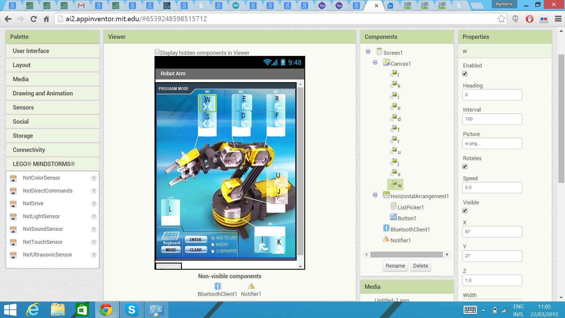
To create the app I used app inventor which is simple to use. I did some of their tutorials at first and once I understood how all the components work, I made my own app.
What my app had to do was send the same signals that my computer did when it was connected to the Arduino, For then the arduino could respond the same way.
Once my app worked, I had to connect the Bluetooth module to the Arduino that was simple as it was four wires involved, Ground, 5V, and two signal wire. Once everything was connected I had to test it.
Step 4: Step 4 Putting It All on a New Board


Once all of that was working, I made a custom circuit board; however it was not as efficient as I wanted, so with my supervisors we decided to use a motor shield instead. The disadvantage of using the motor shield was that it could only hold up to 4 motors and I needed to be able to control up to 6 motors.
So I started by re-writing the code for the Arduino and made sure that the shield worked with four of the motors. Once it did that’s where I had to decide. I had a choice of two options.
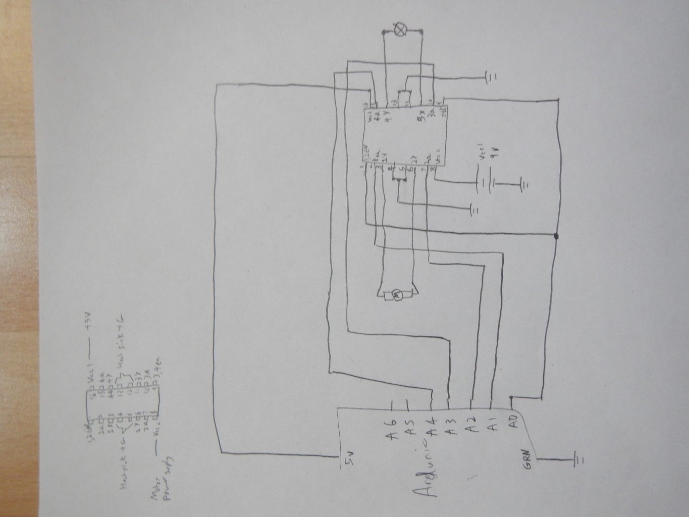
1. I hacked the Arduino board for then I can accept another shield with it in parallel but that meant understanding how a 74HCT595 latch work, and re-writing the code for the microcontroller chip.
2. Modify the motor shield for then I can add a custom circuit board to it.
After some thought and research, I found that I would be easier to just add my own custom board to it. So I had to make some new schematics, as my previous board was two big. So I used the same circuitry as my previous board but made it smaller. To do so I had to hand wire each components together.
Step 5: Step 5 Completing the Robot


Once I had the Arduino shield working with the circuit that I made I had to put everything together. To start off with I laser cut a base to put on the robot for then it can hold everything.
I then neatly tucked all of the wires into the robot and then made them come out just behind the Arduino. I then hot glued the Arduino and my circuit board to the laser cut base. I also added a switch to the battery pack for then I can turn on and off the circuitry. I tried and tuck in as much wire for then it had an appealing look to the final design.
For mor information on the EPQ itself check out my blog on it at; http://myroboticprojects.blogspot.co.uk/
Thanks for reading my first Instructables
Attachments


Participated in the
Robotics Contest

Participated in the
Tech Contest


