

Introduction: Object Counter Using IR


In this small project, we will create a completely automatic object counter with a simple segment display. This project is rather simple and only incorporates simple electronics. This circuit is based on Infrared to detect objects, to find out more about how IR functions, visit my IR Instructables. You can learn all about the basic concepts of IR there.
Supplies
Raw materials: A4 CardBoard (To build the body and base)
Circuit:
Breadboard x1
CD4026BE x2
LM358 x1
2n222/BC547 x1 (or any equivalent transistor)
2pin push-button x1
10k potentiometer x1
220ohm resistor x2
680ohm resistor x2
10k resistor x2
2x Common Cathode 7-segment display
IR LED x1
Photodiode x1
Lots of jumper wires
9v power supply
Tools: Soldering Iron, Wire stripper/cutter, Cutting knife, PVA Glue, Protractor, Ruler etc.
Step 1: Preview


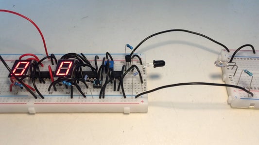
The idea of this project is to create an object counter to count small things such as components, Lego bricks, beads etc. Objects would be dropped onto a ramp, it would roll down into a container at the bottom but will be detected by a pair of IR detectors.
The output of the Photodiode will go through a NOT gate and then into the comparator. The images above show how the IR pair detect an object.
Step 2: The Circuit


The circuit used for this project is not complicated, it uses an OP amp (LM358) as the input regulator for the 7-segment display chip (CD4026BE). I designed the circuit so it has 2 7-segment displays which give it 2 digits or 99 possible objects to count. That should be plenty, but if it's not, then you can link another display which will give you 3 digits, definitely enough.
The button in the circuit is for reset.
The potentiometer is to adjust the sensitivity of the photodiode.
The circuit diagram above is the same as the breadboard circuit. It might be a little difficult to read as it is compressed into a confined space.
NOTE: The transistor in the breadboard circuit image is the wrong way around, but it should still work. I would advise on flipping it around even though some transistors work both ways. Follow the wiring of the transistor in the circuit diagram if you are confused.
Step 3: Circuit Test
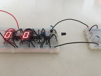

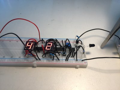
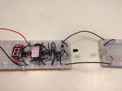
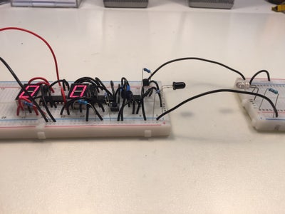
Before you build the circuit into the project, testing it is a smart idea. I have modified the circuit a tiny bit (by changing the IR LED onto a different breadboard to create the IR beam between it and the photodiode). Connect the circuit to a 9v power supply and the digits would light up with two 0s. Next break the IR beam between the IR LED and Photodiode by blocking it with a finger or an object, now one of the digits would turn from 0 to a 1, repeat the process and the circuit will count the number of times the IR beam was broken (objects).
The smart thing to do now is to make this circuit into a PCB, unfortunately, I hade problems with ordering mine so for the rest of this project, I will use the breadboard.
Troubleshoot: If your circuit malfunctions, check:
Wiring,
Component direction (polarity or the way the chips are facing) (Especially the Photodiode)
Power supply,
IR Pair (see if they work together with a simple circuit from my " All about IR" Instructables)
Step 4: The Body


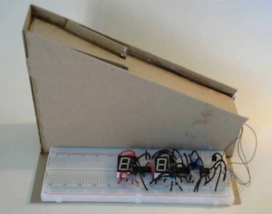
My design is probably not the most visually pleasing one but it works fine.
Cut everything out, size does not really matter but I would recommend the angle of the slope to be between 20 and 45 degrees. The base plate would have the breadboard or PCB mounted on it so there is a minimum size.
The material of the body does not really matter but I would choose something thin and strong such as compressed cardboard.
Step 5: Stick It!


Assemble the structure once everything is cut out. Use tape to hold it together in shape and apply glue. PVA glue is perfect but it takes a while to dry. Now, wait.
Once it is confirmed the glue has dried, peel the tape of and your structure is finished.
Step 6: Add the Circuit
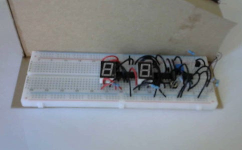
Stick the breadboard with the circuit onto the empty space on the base of the structure. Make sure the 7-segment displays are facing you so you can read the numbers the right way around.
Step 7: Connect the IR Pair

Bend the terminals of both the IR LED and Photodiode at 90 degrees. Solder some wires to the end of the terminals (the wire must be long enough to connect the diode form its mounting place to the breadboard). Next, connect the IR pair to the Breadboard.
Run your circuit again just to make sure your solder joints work.
Step 8: Final Touches


Glue the IR pair onto the slope, make sure they are on both sides and facing each other to create the beam of IR.
Hide the wires by glueing it into the edge of the slope.
Then cut two pieces of cardboard, around 5cm in length and the height of the walls of your slope. Put it in as shown in the last image, hold it down with tape as you apply glue to stick it down.
Once that is done, remove all tape, run the circuit to check it still functions correctly. If you want to decorate it, then this is the time to do it.
Circuit troubleshoot:
If the counter does not count when you break the IR beam (but it was working earlier), then it might be because of the IR beam not been completely blocked, this is caused by some irregular reflections the cardboard creates. This can usually be solved by sticking a tiny strip of black paper under the IR LED so it absorbs any reflecting IR. If this isn't the problem, check if you have short-circuited any of the diodes when glueing them.
Step 9: Finish!

Now it is finished!
Power it up and start counting!

Participated in the
Sensors Contest


