

Introduction: Online Temperature Monitor W/Raspberry Pi


In this Instructable I will show you how you can create a simple temperature monitor to monitor ambient temperature using your Rasberry Pi and a custom data capture board. I will include a sample web application that illustrates some of the ways you can display and analyze the data. I will also show you how to create the data capture board to read the ambient temperature. Finally I will you how to integrate the hardware and software using SPI and operating system tools such as cron.
This Instructable assumes a fair amount of knowledge regarding the Raspberry Pi and Linux in general. There are several commands that I will show you and it's important that you understand basic operating system commands in order to be successful. If you are a beginner with the Raspberry Pi and/or Linux in general you might find this Instructable challenging. I will provide links to tutorials where appropriate in case you encounter a topic that is unfamiliar.
This Instructable will consist of three main parts. In the first part I will describe the necessary services, operating system tools, and configuration. I will provide links where necessary. In the second part I will describe the electrical components and connections and I will go over the breadboard assembly of the data capture board. In the last part I will describe the necessary software and drivers needed for the monitor program and I will show you how to integrate all the parts. I will also explain the example web service and application I created to display the data.
All of the source code will be available online through Github. Links will be provided when appropriate.
Step 1: Software Setup and Dependencies

Before you start it's important that you update your Raspberry Pi to ensure that all the required packages can be found. This can be done with the following command:
sudo apt-get update
In order to get the most out of your Raspberry Pi for this Instructable it's necessary to install a LAMP server on your Raspberry Pi. LAMP is an acronym for Linux Apache MySql PHP which are the names of the components necessary. There are several walkthroughs and tutorials that show you how to do this. The ones I used for this Instructable are http://www.penguintutor.com/linux/raspberrypi-webserver and https://www.youtube.com/watch?v=CEji-qN-TEE. Make sure your webserver is working before moving on.
After your webserver is running you will need to install the development tools. These can be found in the build-essential package:
sudo apt-get install build-essential
You will also need the mysql development tools. These can be found in the libmysqlclient-dev package:
sudo apt-get install libmysqlclient-dev
Another utility that you will need is git.
sudo apt-get install git && sudo apt-get install git-core
Finally you will need to enable the SPI hardware on your Raspberry Pi. To do that you must edit the file /etc/modprobe.d/raspi-blacklsit.conf. You can use your favorite editor to do that, but in this Instructable I will assume nano. The following command will bring up the file in the editor:
sudo nano /etc/modprobe.d/raspi-blacklsit.conf
Once inside the editor you must ensure the following line is commented out:
Save the file and reboot. Once your Rasbperry Pi has rebooted you can check if the SPI interface was enabled successfully by running the following command:
sudo lsmod
If you see spi_bcm2708 in the list then you have enabled the SPI peripheral in your Raspberry Pi. If you don't see it in the list go back over the steps and make sure you didn't miss one. All commands need to be ran as root so make sure you type sudo before each command.
Step 2: Hardware: Part 1 Required Components


- TMP-36 Temperature Sensor (Sparkfun #SEN-10988)
- MAX-144 12bit 2 Channel Analog to Digital Converter
- Two .1uf ceramic capacitors
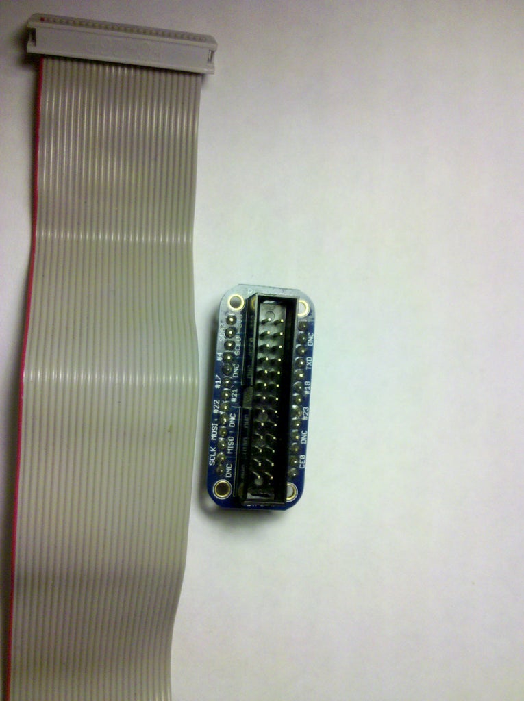
- Raspberry Pi Cobbler Breakout and Cable Adafruit ID: 914 (Optional but Highly Recommended - This Instructable assumes you have one)
- Various jumper wires and connectors
- A breadboard
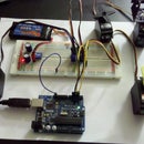
- A Raspberry Pi (I used a Model B for the project, but a Model A is shown in the picture - there shouldn't be a difference)
Step 3: Hardware: Part 2 ADC


- Place the Max 144 on the breadboard. Leave room for the cobbler. A little off center is the best place. Note the orientation!
- Connect the Ref/Vdd and Gnd wires on the Max144.
- Short CH1 and CH2.
- Place .1uf Capacitor (as close to the Vdd lead as you can get it).
Step 4: Hardware: Part 3 TMP-36


- Insert the TMP-36 into the breadboard. Note the orientation!
- Connect Vcc to 3.3v (Again, note the orientation)
- Connect GND
- Add a .1uF capacitor between the 1st and 3rd leads.
- (Optional) 2.2uf Tantalum capacitor. Watch the poarity - positive lead should connect to Vss. Only use if you have noise problems.
- Connect middle lead (pin 2) of the TMP-36 to CH2 (pin 3) of the MAX-144.
Step 5: Hardware: Part 4 Cobbler and Pi Electrical Connection


- Connect 26 pin ribbon cable to Raspberry Pi. Notice orientation of cable in relation to P1 on the Raspberry Pi motherboard. Make sure you match it exactly.
- Connect SCLK to the MAX-144 SCLK (pin 8).
- Connect MISO to the Dout pin of the MAX-144 (pin 7).
- Connect CE0 to the /CS pin of the MAX-144 (pin 6).
- Connect 3.3v pin from Rasbperry Pi to 3.3v rail of breadboard.
- Connect GND of the Raspberry Pi to the ground rail of the breadboard.
- Connect 26 pin to Raspberry Pi Cobbler.
Step 6: Software
The library is very simple and consists of just a handful of functions:
int SpiOpenPort (int spi_device, int mode, int speed);
int SpiClosePort (int spi_device);
int SpiWriteAndRead (int spi_device, unsigned char *data, int length);
The function SpiOpenPort will open an spi device. The choices for spi_device are 0 or 1 which corresponds to CE0 and CE1 for the chip select. The mode specifies the SPI mode - leading clock edge, trailing clock edge, etc... The final parameter, speed, represents the desired speed (in Hz) you want your SPI to communicate at. The underlying system will try to match to the closest or best match for the speed you specify.
The monitor program is not much more difficult. It involves reading 2 bytes from the MAX144. The read is performed twice so we are always operated on CH2 data (which should be shorted to CH1). We create a two byte word with the first byte being the MSB and the second the LSB. We then mask the 12th bit which specifies what channel we read, and finally convert that to a resultant voltage value for conversion to a temperature. The conversion to temperature involves the linear function (V * 100) - 50 which is the conversion function to temperature according to the datasheet.
double read_temperature() {
	double scale = 3.3/4096;
	double voltage;
	unsigned char data[2] =  {0x00, 0x00};
	int value;<br>
	SpiOpenPort(0,0,10000);<br>
	// read twice to get CH2 data<br>	SpiWriteAndRead(0, data, 2);<br>	SpiWriteAndRead(0, data, 2);<br><br>	SpiClosePort(0);

	// convert to a 2 byte word MSB first<br>	value = (((int)data[0] << 8) + (int)data[1]) & 0x0FFF;<br>	voltage = value * scale;<br>	return (voltage * 100) - 50;<br>}
After reading the voltage it's inserted into the MySql table. Before we look at that code though, we have to make a small divergence to MySql and create the database and table structure necessary for the application to function properly.
Download the source from the github repository: https://github.com/scottmccain/tempmonitor
Create the necessary tables and database using the following command (note this only has to be done one time):
? mysql -u root -p -e "create database Piservicedb; use Piservicedb; create table temperatures (id INT NOT NULL AUTO_INCREMENT, temperature double NOT NULL, timestamp DATETIME NOT NULL, PRIMARY KEY ( id ) )";
Change directory to the project root:
cd tempmonitorMake sure you mark the script executable:
chmod +x ./createdb.shThen run the script:
./createdb.shEnter in your credentials (you can change the user if you want by modifying the script) and the database and table structure will be created for you.
Once that's complete you can build the required library files by running:
sudo make library
This will build and install the requisite library and shared object for the temperature monitor. After that you can build and install the monitor program. Before you run build the source code, however, there are a couple of commands you will need to run before hand. The makefile depends on 2 environment variables that must be set before the code will compile or link properly. The variables should be set with the following commands:
[insert command to set vars with mysql_config]
Finally you can build and install the program with the following command:
sudo make && sudo make install
This will build the source code for the monitor program and install it in a location where cron can see it.
Next we will create a crontab entry to start logging temperatures on a timed basis. First open the crontab editor by running the following command:
sudo crontab -e
Once the editor is open scroll to the bottom of the file and insert the following line:
*/5 * * * * /opt/bin/monitor
Save your changes. This will run the monitor program every 5 minutes to log the temperature. You may adjust the entry for your own needs. Please reference the cron man pages for more information.
Congratulations! At this point your Raspberry Pi should be logging temperatures. You can verify that by going into mysql and running a query against the temperatures table in the servicedb database. Next I will show you a simple web service and application I whipped up to display the values from the database.


