

Introduction: Motion Detector With LED for Beginners


This is a simple project I made to test some motion sensors I bought. It will detect motion and light an LED when it does. This should only take 20-30 minutes start to finish and is a perfect project for beginners. Enjoy!
Step 1: Gather Supplies
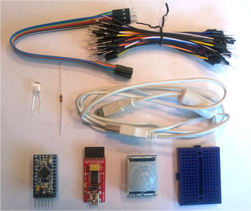
First, gather your supplies
- Arduino Pro Mini (or any other Arduino board)
- if using a Pro Mini you will need an FTDI chip and USB mini cable to upload your sketch
- Jumper Wires
- 1 Breadboard
- 1 blue LED
- 1 22 Ohm Resistor
- 1 PIR motion sensor (PIR stands for passive infrared)
Step 2: Wiring and Adjustments


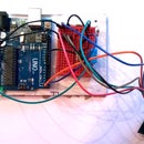
You will need to connect the LED and PIR sensor to the Arduino board. The PIR sensor I used has the center pin as the signal, the left for the 5V supply, and right for Ground. Wire the center line to digital pin 10 and the power and ground lines of the PIR to the 5 V pin and to the GND pin on the Pro Mini.
The LED should be connected to digital pin 3 (and don't forget the necessary resistor for the LED you're using). In my case I used a blue LED with a 22 ohm resistor.
The sensor reads more sensitively when motion is horizontal across the sensor rather than vertical according to the data sheet but I haven't had any problems with vertical motion detection.
The sensor has two different trigger methods, single trigger or repeating trigger which can be changed by adjusting the jumper in the top right. As shown it is set to single trigger which means when it senses motion it will set the signal line to high (3.3 V) for 2.5 seconds and then automatically go back to low until it detects motion again. In repeating trigger method the sensor will trigger high when motion is detected and stay high for a set amount time which can be adjusted by the timing screw. If motion is detected during that time, the timing resets to 0. In this way the signal can be kept continuously high while there is motion in front of the detector.
The default delay setting for the repeating trigger is 2.5 seconds. This can be adjusted up to roughly 5 minutes by turning the timing screw clockwise or down to as low as 0.3 seconds by turning it counterclockwise. Likewise, the sensitivity may be adjusted up by turning the sensitivity screw clockwise up to roughly 7 meters and decreased by turning the sensitivity screw counterclockwise down to about 3 meters.
Step 3: Code!
The code for this project is pretty simple. According to the data sheet for the PIR sensor it takes roughly 1 minute to initialize so the setup function has 60 seconds of delays during which time the LED will blink off and on in 3 second intervals. Once the sensor is initialized it will trigger high whenever it senses motion which will turn the LED on for 5 seconds. After the 5 seconds it will try to read again and the LED will stay lit if more motion has been detected or go low if there is no motion. The code can be found on my GitHub page and I have copied it below.
int LED = 3;
int PIR = 10;
void setup() {
// initialize digital pin 3 as an output for LED
pinMode(LED, OUTPUT);
//initialize digital pin 10 as input for PIR
pinMode(PIR, INPUT);
//initialization time for PIR sensor to warm up
//blink LED to show that something is happening
for(int i = 0; i < 10; i++) {
digitalWrite(LED, LOW);
delay(3000);
digitalWrite(LED, HIGH);
delay(3000);
}
}
void loop() {
//read PIR sensor, if High light LED for 5 seconds
//if low, check again
if(digitalRead(PIR) == HIGH) {
digitalWrite(LED, HIGH);
delay(5000);
} else {
digitalWrite(LED, LOW);
}
}
Step 4: Program Your Arduino

It's not quite as easy to upload a sketch to an Arduino Pro Mini as it is to one of the other varieties of microcontroller that have USB ports directly on them. However it is still relatively straightforward and just a few tweaks to the Arduino IDE are needed to get it right.
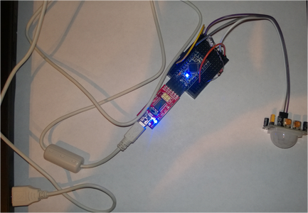
First, make sure you have a USB mini cable, not micro! If you have the FTDI chip and Arduino Pro Mini board I linked to in the supply list it's as simple as hooking the FTDI right onto the programmer pins on the end of the mini and then connect the USB to the FTDI and to your computer as shown in the image.
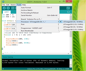
In the Arduino IDE paste the code in and select the Arduino Pro Mini board in Tools -> Boards. In Tools -> Processor Select ATMega328, 5 V. Now you can compile and upload your sketch as usual.
Step 5: Use Your Motion Sensor!
Congratulations, you've made a motion detector! Now you can plug in your motion sensor and watch it work. In the future I will be making several of these which will communicate via RF receivers with a board that will be able to display if there is motion detected at other sensors. I hope this Instructable helped you get started with your motion sensors and Arduino

Participated in the
First Time Author Contest


