

Introduction: Palm Arduino Kit


UPDATE: Read about the first journey of Palm Arduino Kit, here!
I do travel many times a year, sometime I went with family, took relatives, friends, to places in US, for days, may be for weeks, even for a month, when I traveling aboard to visit my family once a year.
Previously, I left my Arduino project(s) untouched for the duration of the traveling. And most of the time, after i got back, I had to start the project over, because I was already forgot where it was left off. During the time of traveling when I got some idea for prototyping, I could not do anything since I did not have Arduino stuffs at hand. And I missed working on the project(s) very much while I was traveling.
This time I planned to do something about it! And this was I prepared them for. A Palm Arduino Kit.
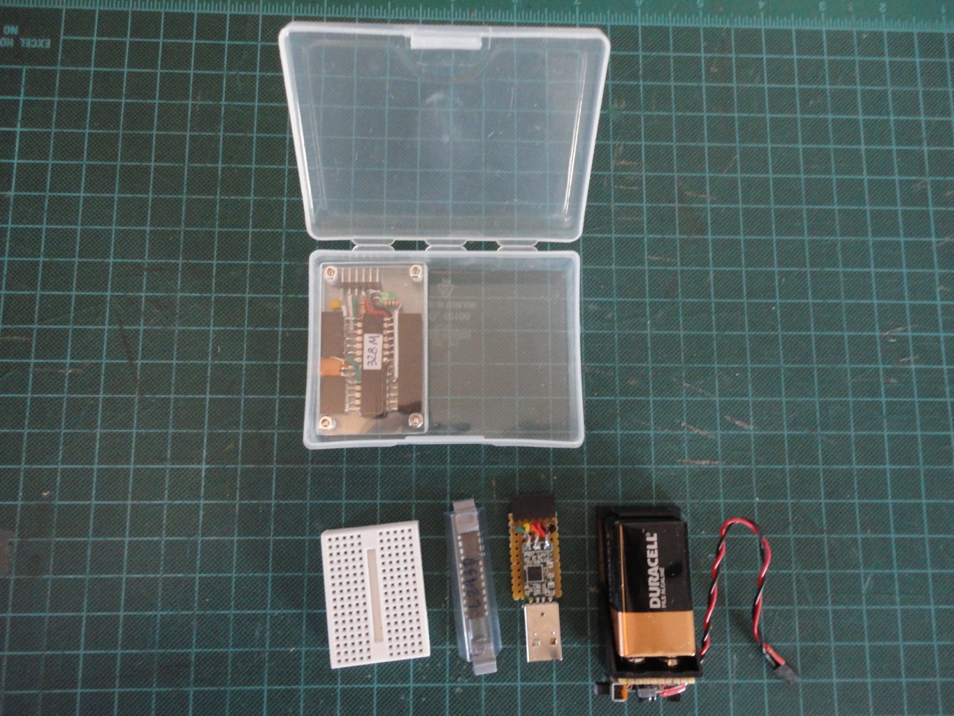
The kit contains:
A DIY palm size Arduino compatible board
A mini breadboard (Commercially available)
A DIY 5V Portable Voltage Regulator (Step 6)
A MOD FTDI cable (See my FTDI adapter instructables details here.)
A MOD 2" Long Antistatic IC Container.
2.25" Wide x 3.75" Long x 1" Hinge Plastic Box (Commercially available)
Palm Arduino
Whenever I look at 28-pin DIP ATMega328 IC, I always wonder do I have to use it this way all the time, with the pins hang out beside it body. Could I just straighten it out and do something similar to Freeform Arduino? And don't have to use PCB just like the Freeform Arduino, but make it more portable than Freeform Arduino. The other criteria that I use to design this palm Arduino is that it would be small enough to be with some other components to be fit inside 2.25" Wide x 3.75" Long x 1" Hinge Plastic Box.
So the Palm Arduino is born! And I made it to be only 1.5" wide x 2.5" long x 0.5" thick.
Step 1: Parts and Tools

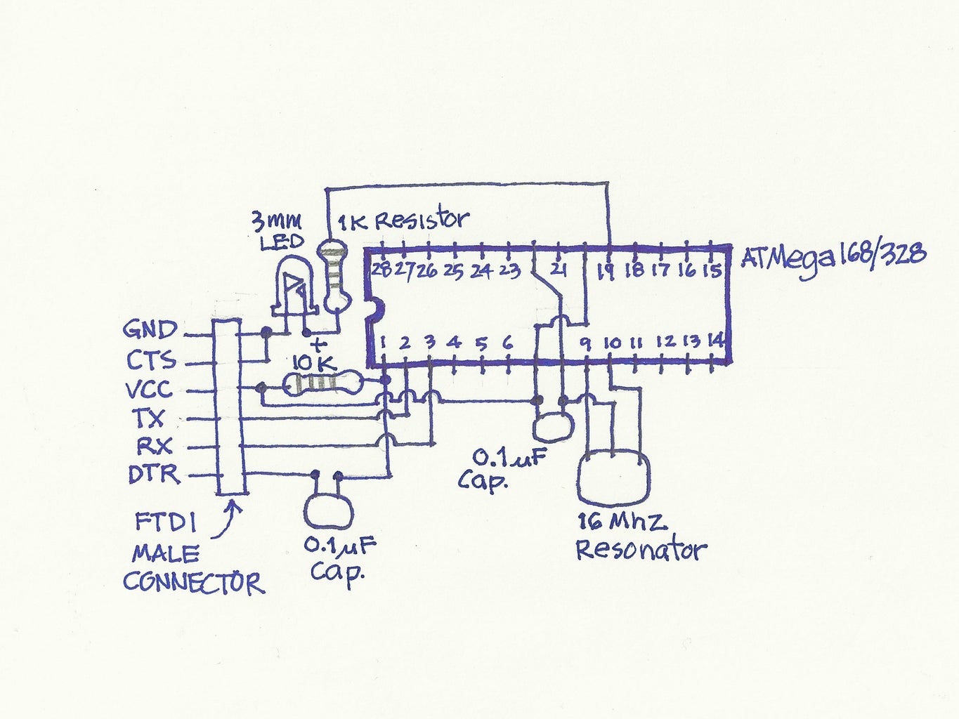
The schematic for the palm Arduino is exactly the same as my Freeform Arduino.
And I would like to thank ColorBomb, an Pro Instructables friend, who volunteer to make the schematic in the better format than my had drawn schematic. Thanks for your time and generosity.
Parts
Arduino compatible:
1 no. ATMega328P with Arduino Bootloader
1 no. 3mm Green LED
1 no. 1K Resistor
1 no. 10K Resistor
1 no. 16Khz Resonator
2 nos. 0.1uF Capacitor
1 no. 1x6 Male Header
1 no. 1x14 Female Receptacle
1 no. 1x4 Female Receptacle
1 no. 1x6 Female Receptacle
2 nos. 1.5" wide x 2.5" long, 1/8" thick clear Acrylic sheet
Plastic Standoffs
Some hookup wires
4 nos. 2-56 Round-Head Machine Screws (Radio Shack# 64-3010)
4 nos. 2-56 Steel Machine Hex Nuts (Radio Shack# 64-3017)
Portable 5V Regulator
(See details instructables here)
9V Batterry
9V Battery Holder
Slide switch
78L05 Voltage regulator, package: TO-92
100uF Electrolytic capacitor
10uF Electrolytic capacitor
1N4001 Diode
2-pin Female receptacle
Hookup wire
5/8" x 1" Perf board
5/8" x 1" Double sided foam tape
Tools
The tools that I used in this project are:
Solder iron and Solder station
Hookup Wire
Diagonal Cutter
Pliers
X-Acto Knife
Wire Stripper
SolderSucker
Step 2: Straighten the Pins
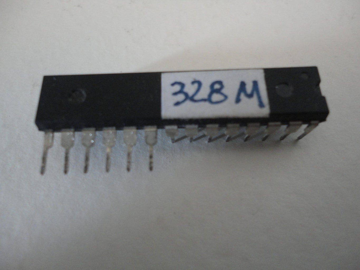


First, I used the needle nose pliers to bend the straighten all tithe pins of ATMega328P IC out horizontally.
Be careful when bending the pins out, too much force could break the pin. Take your time, do it gently.
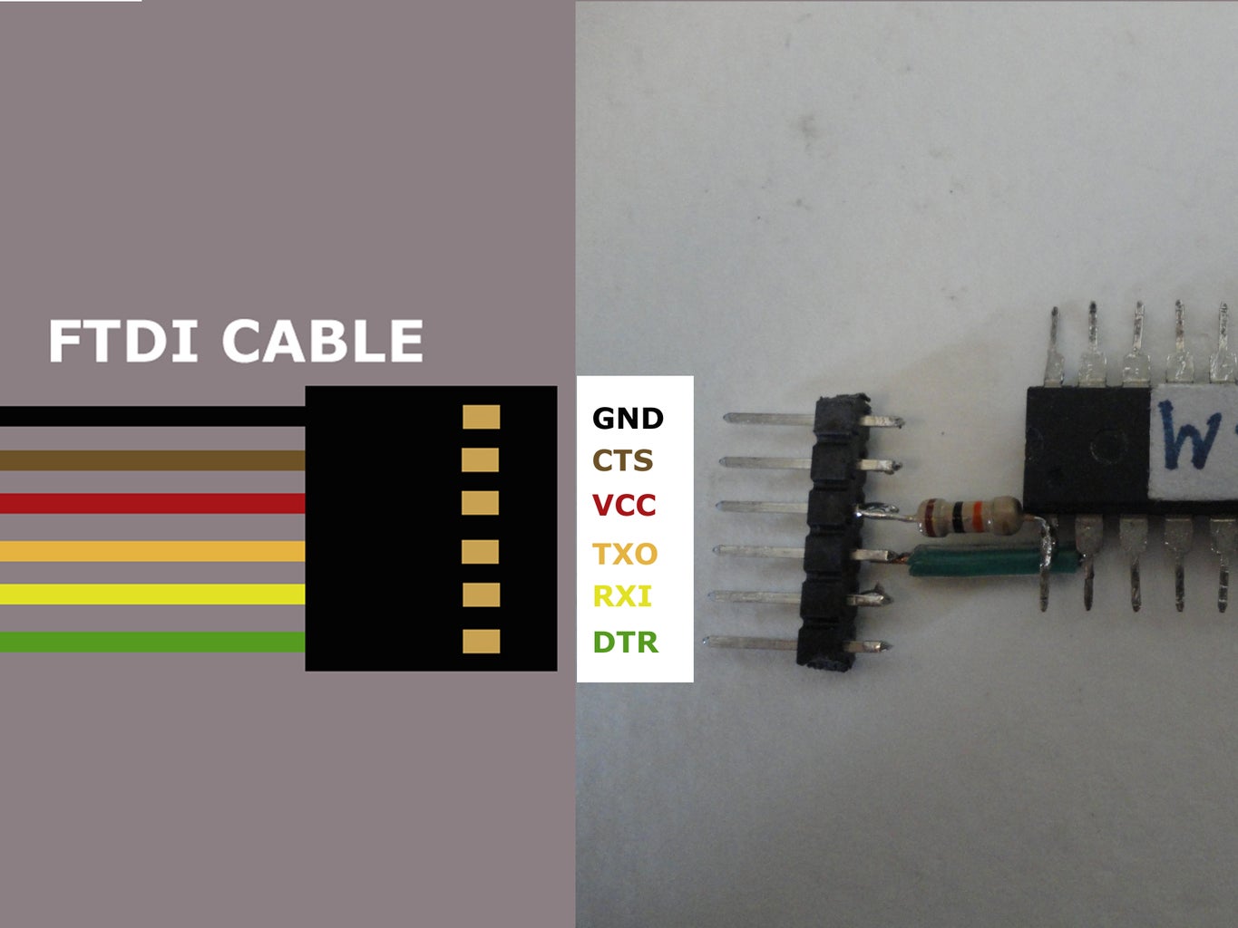
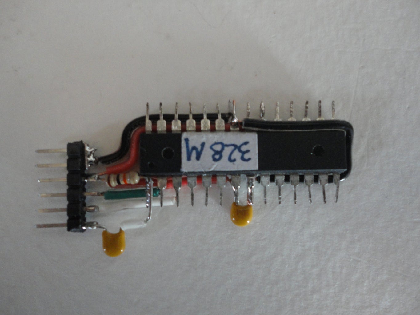
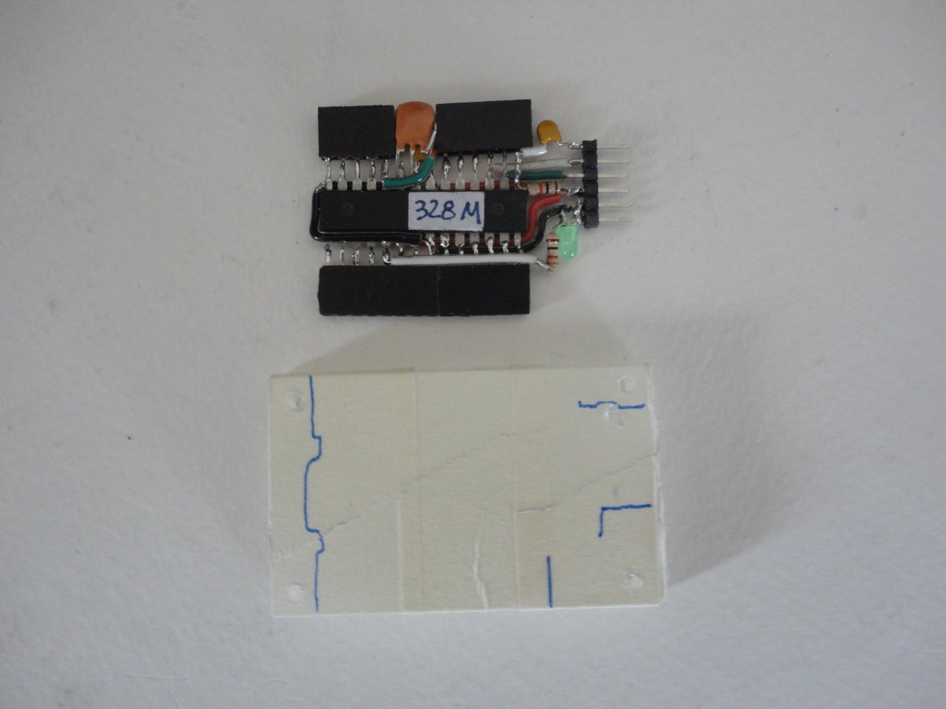
After all the pins were straightened out, I soldered a lead of 10K resistor to pin#1 of micro controller. And I soldered another lead of the resistor to VCC pin of 6-pin,FTDI male header. (See diagram on picture 4)
Next, I connected TX pin of 6-pin, FTDI male header to RX Pin of micro controller (pin#2). And I connected RX pin of 6-pin, FTDI male header to TX pin of micro controller (pin#3)
Then, I soldered a lead of 0.1uF capacitor to DTR/RTS pin of 6-pin, FTDI male header. And I connected another lead of capacitor to RESET pin (pin#1) of micro controller.
Step 3: Added Power and Ground


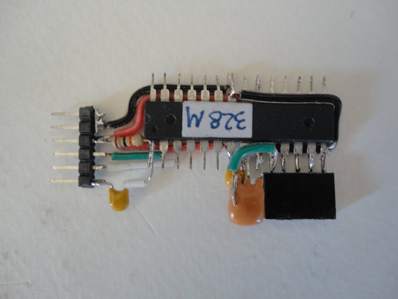
Next step, I connected the GND and CTS pins of 6-pin, FTDI male connector to pin#20 and continue to pin#8 of ATMega328P.
And I connected VCC pin of 6-pin, FTDI male connector to Pin#22 and also wired it to pin#7 on ATMega328P too.
Then I soldered 0.1uF capacitor horizontally to pin#7 and pin#8 on micro controller. (Picture 2)
Picture 3 showed how I soldered the 16 KHz resonator onto the micro controller. First, I aligned the middle pin of the resonator, which laid flat perpendicular to micro controller and on top of 0.1uF capacitor, to pin#8 of micro controller, and soldered them together.
Then I soldered the right most pin of the resonator to pin#9 of micro controller.
I bent the left pin of resonator up vertically, then connected this pin to pin#10 of micro controller with hook-up wire.
Step 4: Bring Out the Pins


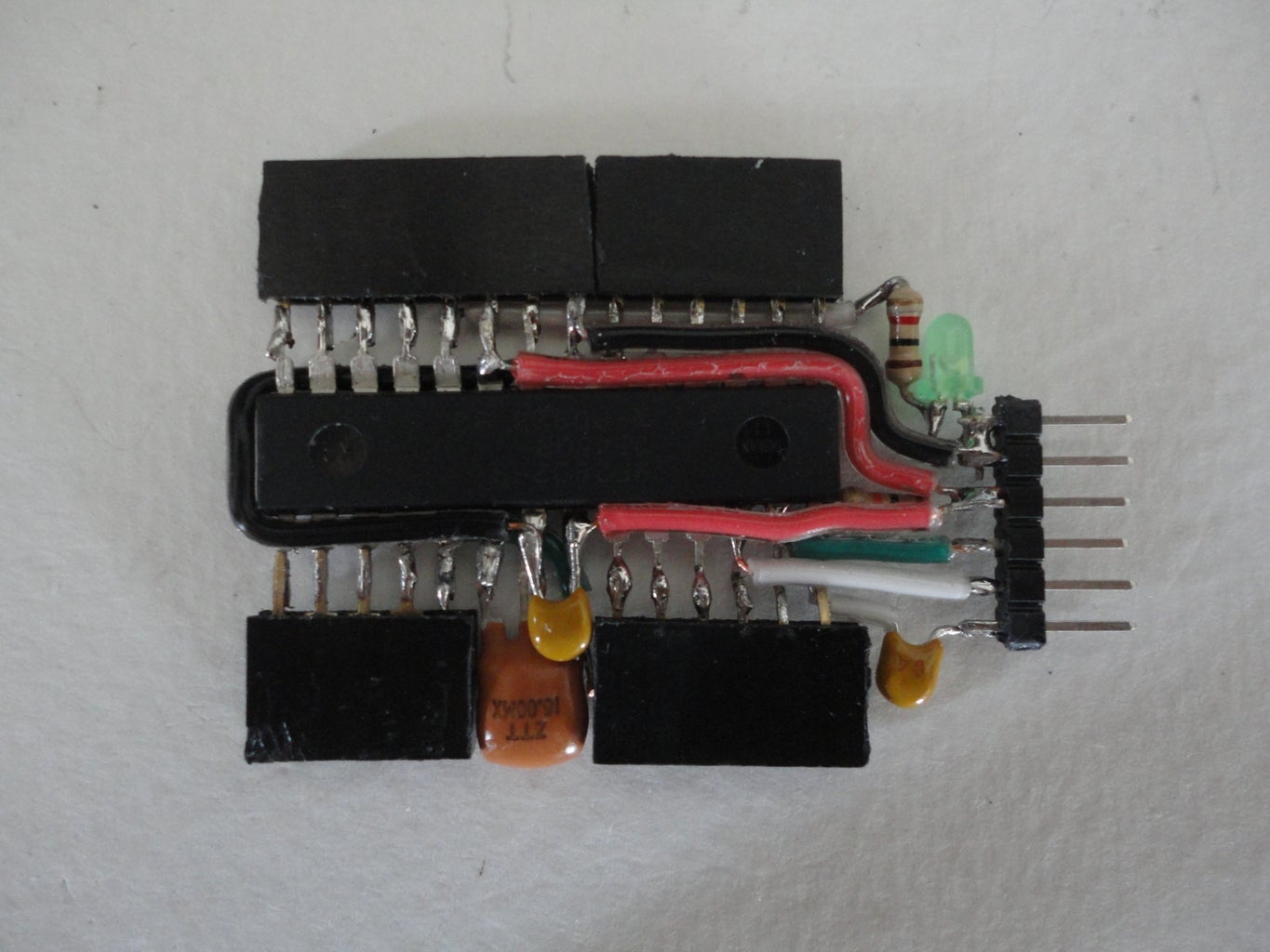
Soldered 1x4 Female receptacle to pin#5, 6, 7, 8 of ATMega328P.
Soldered 1x6 Female receptacle to pin#1, 2, 3, 4, 5, and 6 of ATMega328P.
Soldered 1x14 Female receptacle to pin 9, 10, 11, ..., 26, 27 ,28 of ATMega328P respectively.
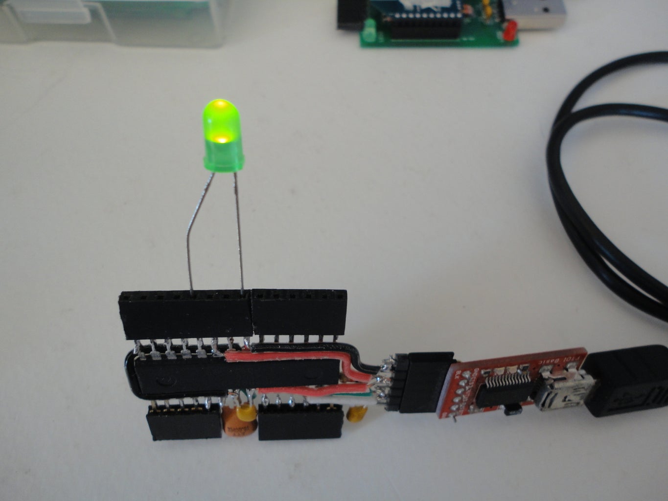
Tested!
Inserted 5mm LED the Positive lead of LED goes to pin 22 (GND pin nest to A0), and the Negative lead of LED goes to pin#19 (D13).
Connected the 6-pin connector of FTDI cable to our Arduino, make sure that the BLACK wire on FTDI connector goes to the GND pin on Arduino's connector.
Then I uploaded the blink.ino from the Basic sample of Arduino IDE.
The LED blinked! Voila, it worked!
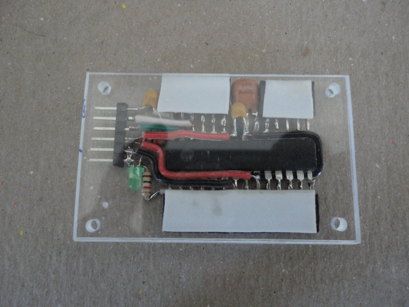
Later I decided to added 3mm test LED, by laid it horizontally. Then connected Positive(+) pin of the LED to GND pin of 6-pin, FTDI male connector, and connected Negative(-) pin of the LED to 1K Resistor. And I connected the other lead of 1K resistor to pin#19 (D13) of ATMega328P (picture 5).
Step 5: Make the Case or Cover


I cut 2 nos. 1/8" thick Acrylic to the size of 1.5" wide x 2.5" long.
Blur the edges and clean them, before wrapped them together tight with masking tape.
This way, I could drill the holes that would located exactly on the same spot on both top and bottom cover.
Before I drilled four holes at the corners. I marked the shape of the Arduino onto the cover. So the holes would not be blocked by the Arduino and it would have enough space for the plastic standoffs.
I drilled the holes just big enough for 2-56 machine screws, I used rounded head screws.
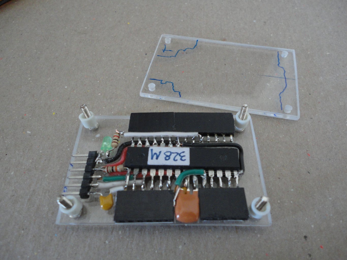
I prepared three pieces of double sided foam tape and used them to secure the Arduino to bottom piece of Acrylic cover (Picture 5).
And I installed the four 2-56 screws from the bottom cover. Then inserted the standoffs, I trimmed the height of those standoffs to be about the height of the body of the ATMega328 before closed the top cover with the 2-56 hex nuts.
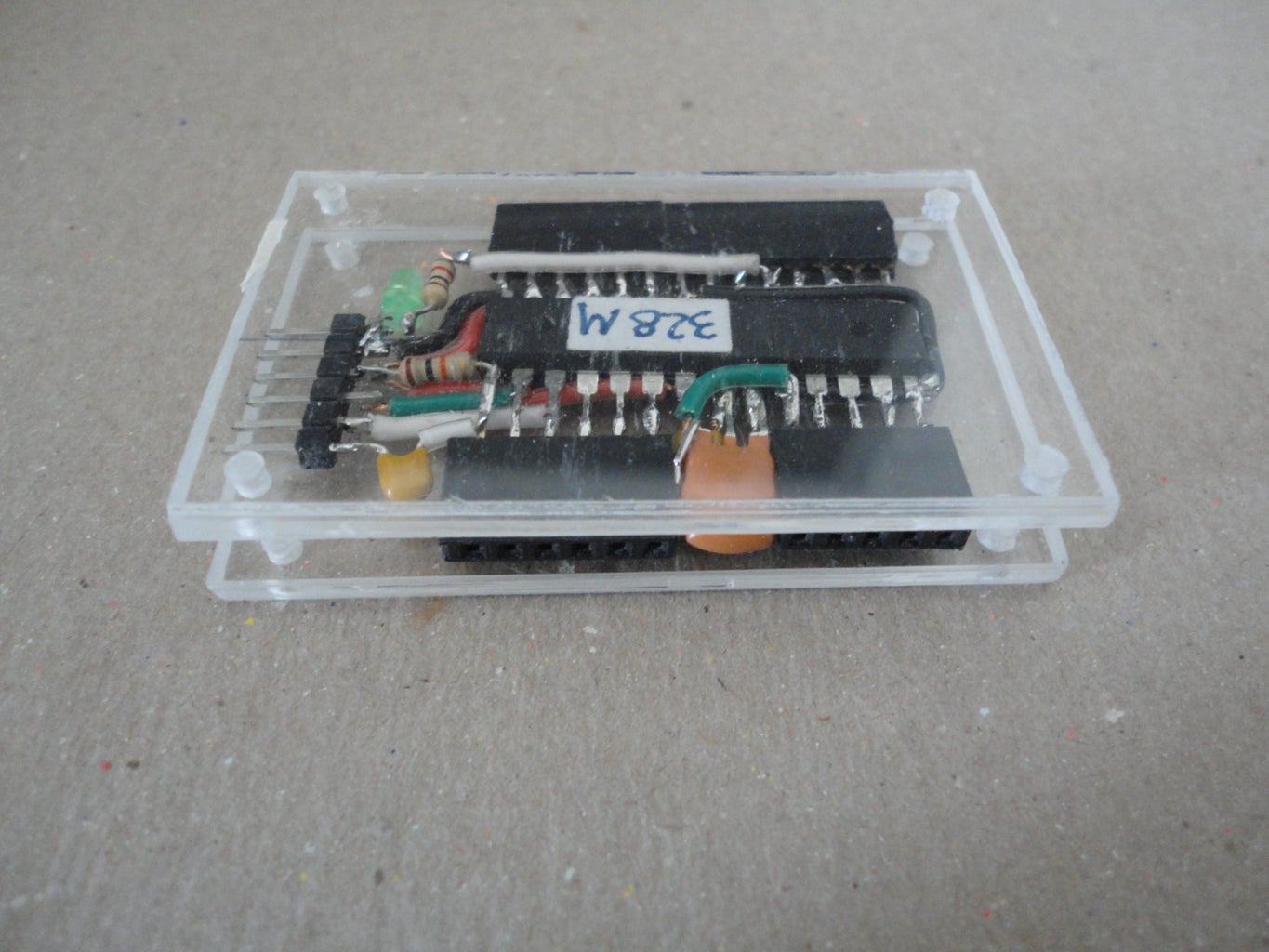
I added the pins label sticker on later. So I do not have to find out which pin is which, and prevented me from inserted the FTDI cable (in my case FTDI dongle) in the wrong direction!
The 2-56 screws extruded out a little farther than needed. So I trimmed them out to flush with the hex nuts. And blurred them with the sand paper.
Again, I tested the Arduino. It's working properly!
Step 6: Portable 5V Regulator
Please follow the link below to see how I made this 5V Portable Voltage Regulator from 9V Battery.
Portable 5V Regulator
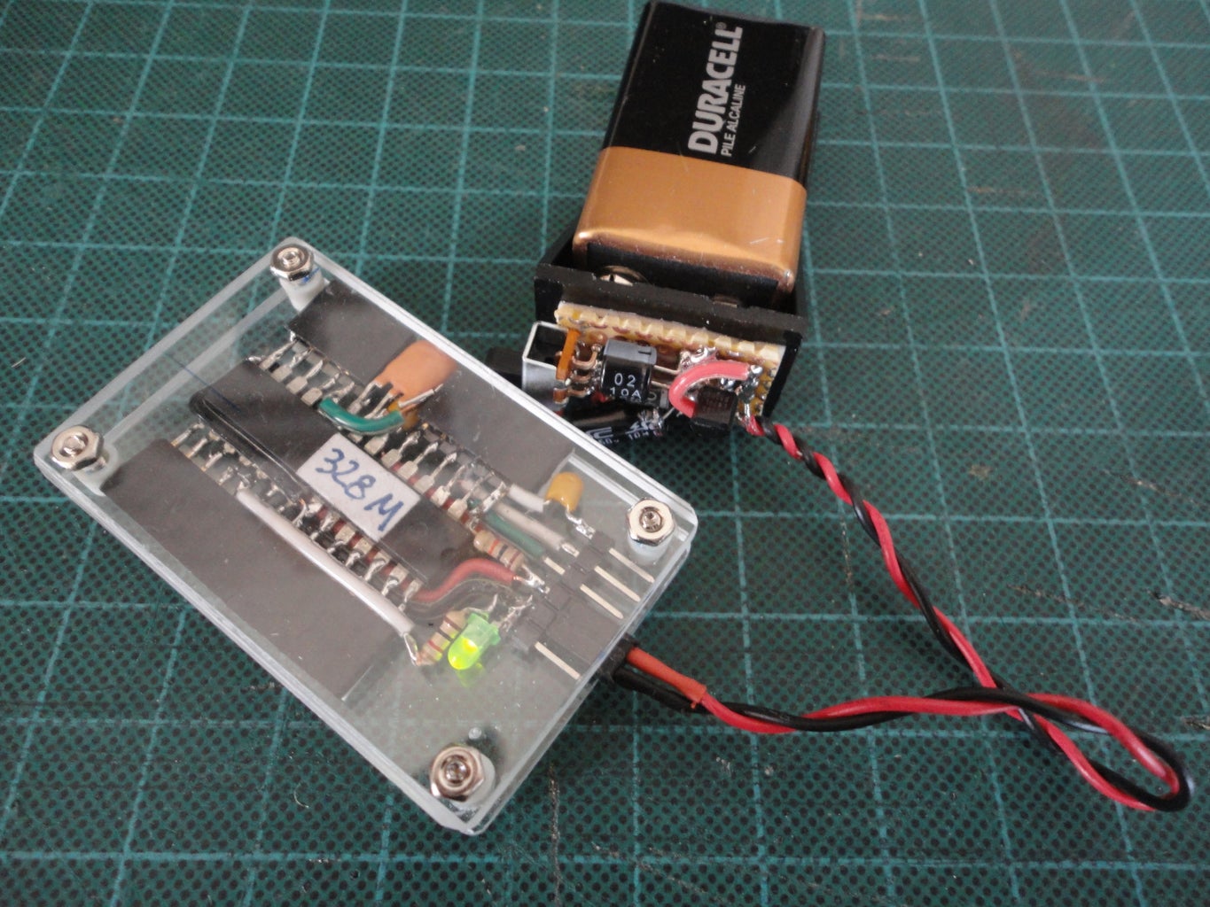
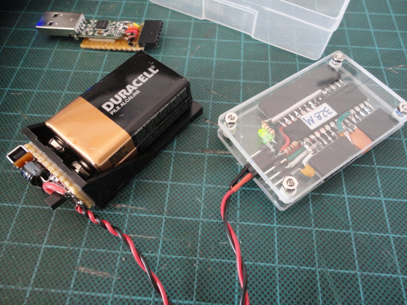
Picture 2 and 3 show how to connect the palm Arduino to the 5V Portable Voltage Regulator.
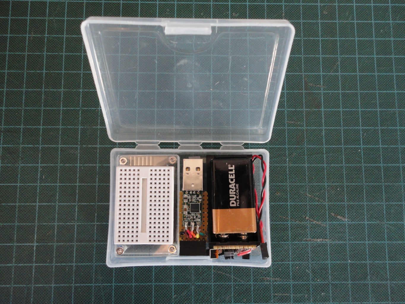
Step 7: Complete Kit


Complete Kit
Pocket Arduino
5V Voltage Regulator
My FTDI Cable MOD.
Mini Bread Board
2.25" Wide x 3.75" Long x 1" Hinge Plastic Box
2" Long Antistatic tube for spar IC, for example LM555, L293D (thoese are in the tube as shown)
Now, I am ready to travel with my pocket Arduino! Of course I'll have a bag of jumper wires pack ready in my laptop case as well.

Finalist in the
Pocket-Sized Contest

Participated in the
Hurricane Lasers Contest


